What a resistance meter actually measures
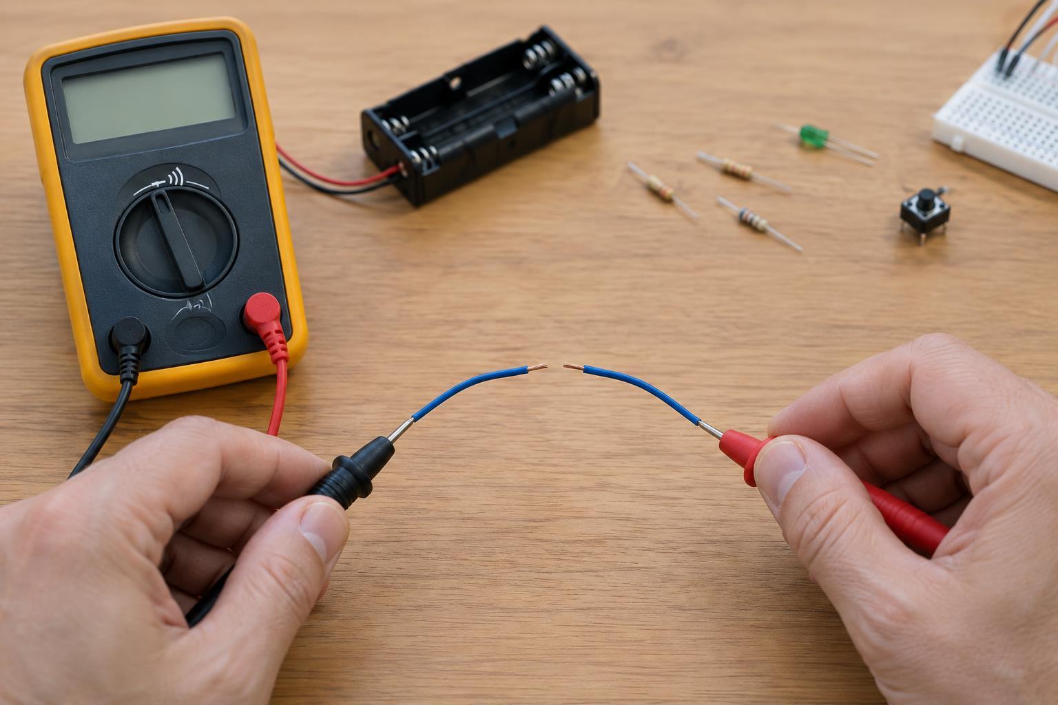
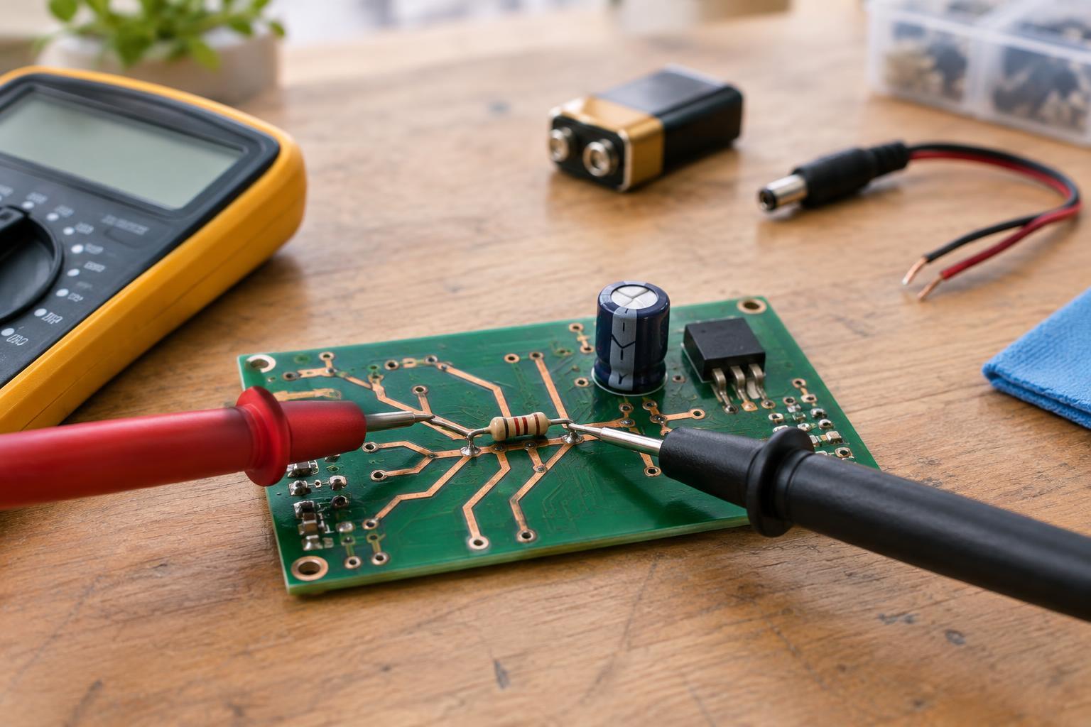
In resistance mode, a multimeter applies a small test signal through its probes and uses the response to estimate resistance. If a resistor is disconnected from a circuit, the meter can measure that resistor directly. Once the resistor is soldered onto a board, however, the probes may also connect to traces, other components and alternate routes between the same two points. The display describes what the meter sees across its probes, not necessarily the value of the one part you intended to test.
This distinction matters when troubleshooting. An unexpected reading is a clue, but it is not by itself proof that a resistor has failed. Before comparing a displayed value with the bands or markings on a component, consider what else is connected to each end.
Parallel paths can pull a reading down
Suppose two 10-kilohm resistors connect between the same two points. Measuring across either one while both remain connected gives a combined resistance of about 5 kilohms. Neither resistor needs to be faulty: the meter's test signal can travel through both paths. A board may contain less obvious parallel routes through switches, coils, indicators or other parts, so its measured value may differ from the value printed on a resistor.
A lower-than-expected in-circuit reading is therefore often inconclusive. A reading close to the marked value can be useful, but it still does not rule out every fault elsewhere in the circuit. A circuit diagram, if available, helps identify alternate paths. Without one, following visible traces and comparing the reading at related points can help you form a hypothesis rather than a verdict.
Other components can make the number move
Not every part behaves like a fixed resistor. A capacitor can briefly draw the meter's test signal while it charges, causing the displayed resistance to change or rise toward an overload indication. A diode or transistor may conduct differently depending on probe direction and the meter's test conditions. Those behaviors can make a resistance reading unstable or apparently inconsistent without indicating a bad component.
Continuity mode has similar limits. Its beep usually means the meter detected a path below its chosen threshold; it does not tell you which path carried the test signal or whether that path will work correctly when the device operates. For semiconductor checks, a meter's diode-test mode may be more informative than resistance mode, but connected components can still affect the result.
Never use resistance mode on a powered circuit
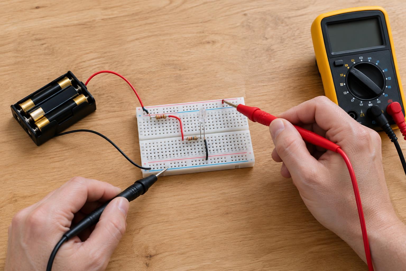
Resistance and continuity modes are intended for unpowered circuits. External voltage can interfere with the meter's test signal, produce meaningless readings and potentially damage the meter. More importantly, touching probes to an energized circuit can create a short or expose you to an electrical hazard. Do not assume that a device is safe to probe just because its switch is off.
For beginner troubleshooting, stay with accessible, low-voltage, battery-powered projects. Disconnect the battery or other power source before resistance testing, and check for remaining voltage only if you know how to use a suitable meter safely. Capacitors may retain charge after power is removed. Do not open or probe mains-powered equipment, power supplies or equipment with large capacitors as a beginner; seek qualified help instead.
A better way to investigate a surprising reading
First, disconnect power and confirm that the circuit is within your skills and equipment limits. Check that the meter leads are in the correct sockets and that you selected the intended mode. Note the probe locations, the displayed value and whether it changes over time or when the probes are reversed. Then look for a plausible parallel path before deciding that a component is defective.
If you need to confirm the value of a resistor in a safe low-voltage project, measure it out of circuit. Removing one end from the board can break parallel paths, but soldering and component removal bring their own risks, including damaged pads and hot-tool burns. If you are not comfortable doing that, leave the component in place and treat the in-circuit reading as a limited clue. Good troubleshooting combines several observations; it does not ask one resistance reading to answer every question.