Start with a safe, defined circuit
This guide is for accessible 3–5 V circuits powered by batteries or an appropriate low-voltage USB supply. It is not a procedure for probing wall outlets, mains wiring, the inside of a mains-powered adapter, or the primary side of any power supply. A low-voltage device can still be damaged by a slipped probe or a shorted battery, so work on a clear, dry surface with good lighting. If a battery swells, leaks, or becomes hot, stop and disconnect it if you can do so safely.
Before measuring, identify the intended path: source positive, any connector or switch, the circuit’s positive supply connection, and the part that appears unpowered. Also identify the circuit’s ground, usually connected to source negative. A board may have several ground points, but do not assume that every dark wire or metal surface is ground. Use a labeled ground test point or a connection you can confidently trace to source negative.
Set up the meter for DC voltage
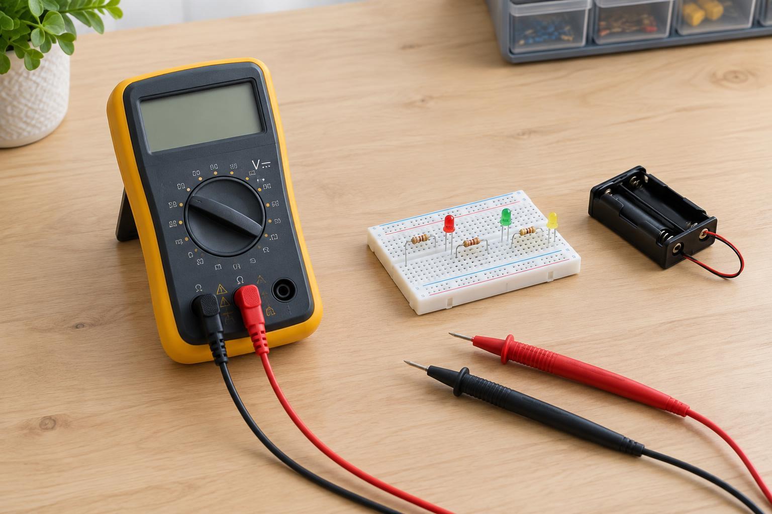
Plug the black lead into the meter’s COM jack and the red lead into its voltage jack, often marked V. Select DC voltage, shown on many meters as V with a straight-line symbol. If the meter is not autoranging, choose a range above the expected supply voltage. Never leave the red lead in a current-measurement jack for this task: touching the leads across a power source in that configuration can create a short.
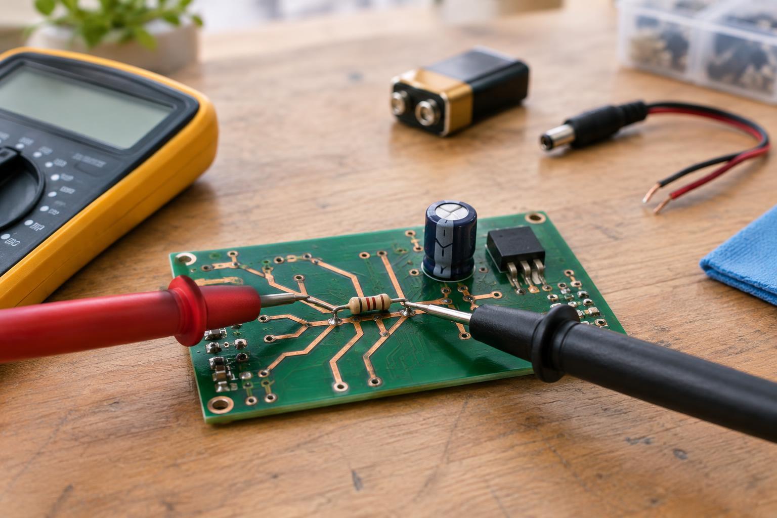
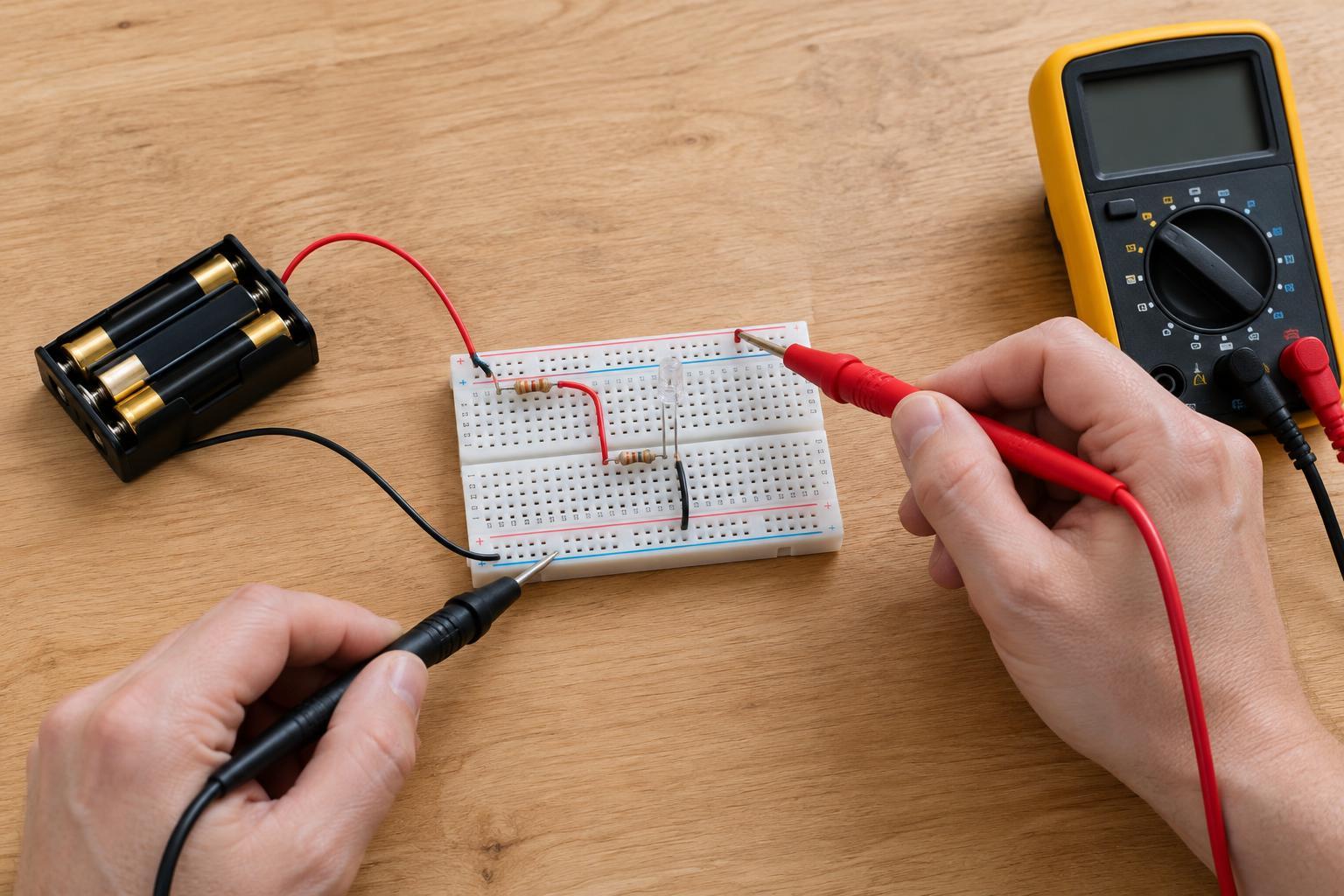
Voltage is measured between two points while the circuit is powered. For a straightforward circuit, keep the black probe on the known ground reference and touch the red probe to one point at a time along the positive power path. Use only accessible contacts; do not force a probe into a connector. If the tips are likely to slip across neighboring pins, power down and arrange a safer way to reach the point before continuing.
Follow the power path one step at a time
First, measure directly across the source terminals. A reading near the source’s expected voltage shows what is available at that moment; it does not prove the source can maintain that voltage under load. If the reading is unexpectedly low, verify that the meter is set correctly and check battery orientation or the supply connection before investigating the board.
Next, measure at the circuit side of the power connector, then at both sides of the switch if there is one. Keep the black probe on the same ground reference where practical. With a working switch turned on, its input and output should normally be at similar voltages. If voltage is present at the input but absent at the output, the switch, its contacts, or its connections deserve closer inspection. Follow the same pattern through any accessible fuse, protection component, or cable connection, and finally measure at the supply pin or terminals of the part that seems unpowered.
Record each point and its reading rather than relying on memory. The useful clue is often the transition between two nearby points: expected voltage at one, little or none at the next. On a circuit with voltage regulation, however, a lower voltage after a regulator may be intentional. Compare readings with the voltage that section is designed to receive, not automatically with the source voltage.
Interpret unexpected readings cautiously
If voltage is present at the source but low everywhere downstream, check the positive connection and the ground return. To test for a missing ground connection with power on, place the red probe on a known positive point and compare readings using ground points on either side of the suspected connection. A changed or unstable reading may indicate a poor return path, but moving the black probe also changes the reference; confirm exactly which two points each reading represents.
A voltage that looks normal with the circuit disconnected but falls sharply when it is connected may indicate a weak source, excessive load, or a poor connection. It does not, by itself, identify a faulty component. Likewise, an unexpected zero reading can result from a poor probe contact or the wrong reference point. Repeat a surprising measurement before drawing a conclusion.
Voltage checks locate where to investigate; they do not replace inspection. With power disconnected, look for loose connectors, reversed batteries, damaged wires, and visible corrosion. If you need a continuity test, remove power first and follow your meter’s instructions. Do not use continuity mode on a powered circuit.
Know when to stop
Power down before moving clips, reseating connectors, or changing wiring. If a component or battery heats unexpectedly, there is a burning smell, or you cannot reach a point without risking a short between adjacent contacts, stop testing. For a small 3–5 V circuit, a short list of labeled voltage readings is often more useful than repeated probing: it shows the last place power was present and the first place it was missing. That gives you a focused, safer starting point for the next inspection or repair.