What a continuity test tells you
Continuity mode checks whether electricity can pass between two points along a path. On many multimeters, a connected path produces a beep and a low resistance reading. A broken path, often called an open circuit, produces no beep and may display “OL” or another over-range indication. The exact beep threshold and display vary by meter, so treat the sound as a quick clue rather than a complete diagnosis.
This method is useful when a low-voltage project has a wire that appears connected but a device does not respond. The fault might be a broken conductor inside its insulation, a loose crimp, a damaged connector, or a solder joint that has separated. A continuity test can show which part of the path needs closer inspection; it cannot, by itself, prove that every part of the circuit will work under load.
Make the circuit safe to test
Use continuity mode only on an unpowered circuit. Switch the project off, unplug its power supply, and remove or disconnect batteries. Capacitors can retain a charge after power is removed, so do not probe a circuit if you are unsure how it stores energy or whether it is safe to handle. Never use this procedure inside a mains-powered appliance or on household wiring; those require different precautions and appropriate expertise.
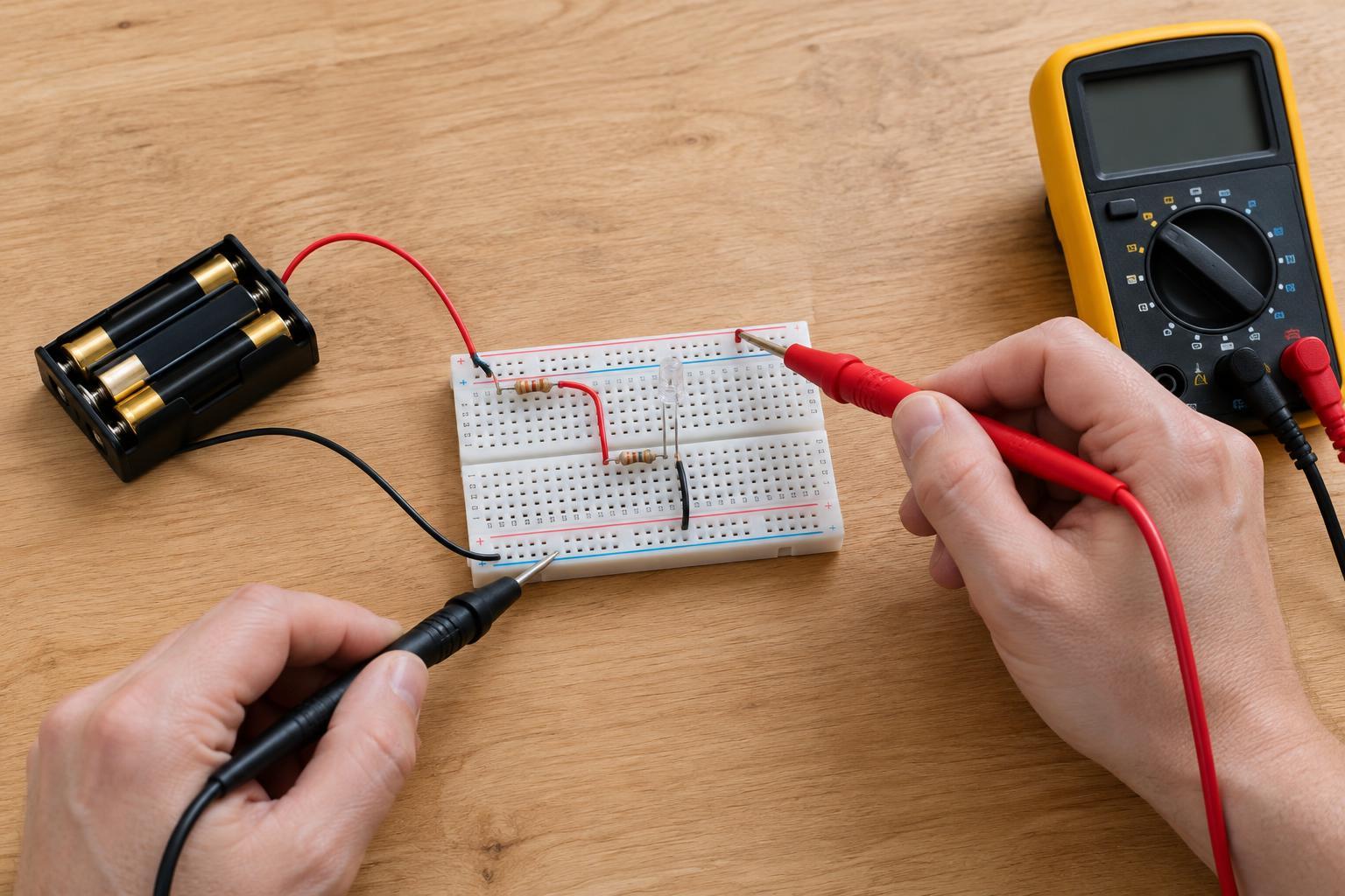
If possible, disconnect at least one end of the suspect wire from the rest of the circuit. This helps prevent current from taking another route through connected components and giving you a misleading beep. Before probing, look for simple clues such as a partly seated plug, a pin pushed back into a connector, or insulation damaged where the wire bends. Do not bridge a suspected break with a tool while power is connected.
Check the meter, then test the wire
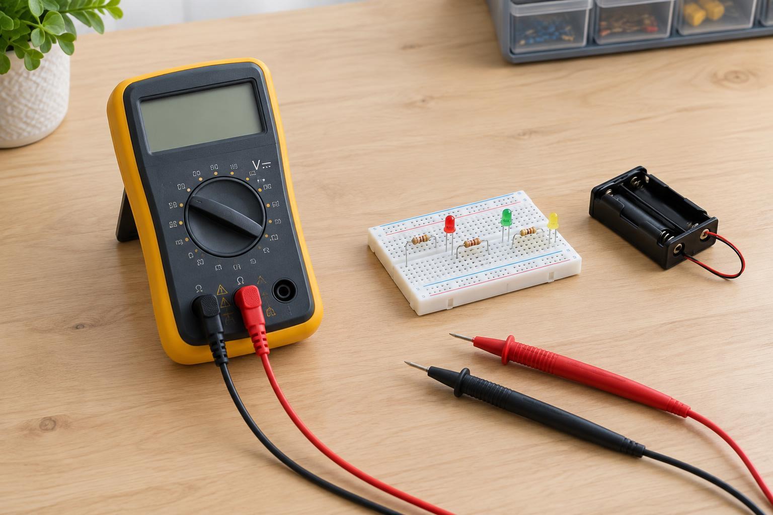
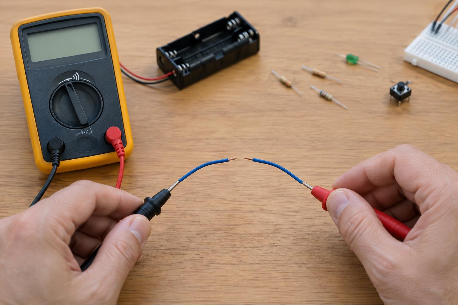
Insert the meter leads into the correct sockets, usually COM and the socket marked for voltage and resistance. Select continuity mode, often marked with a sound-wave symbol. Touch the probe tips together: the meter should beep or show a very low reading. Separate them and confirm that it indicates an open path. This quick check tells you the meter and leads are responding before you rely on a result.
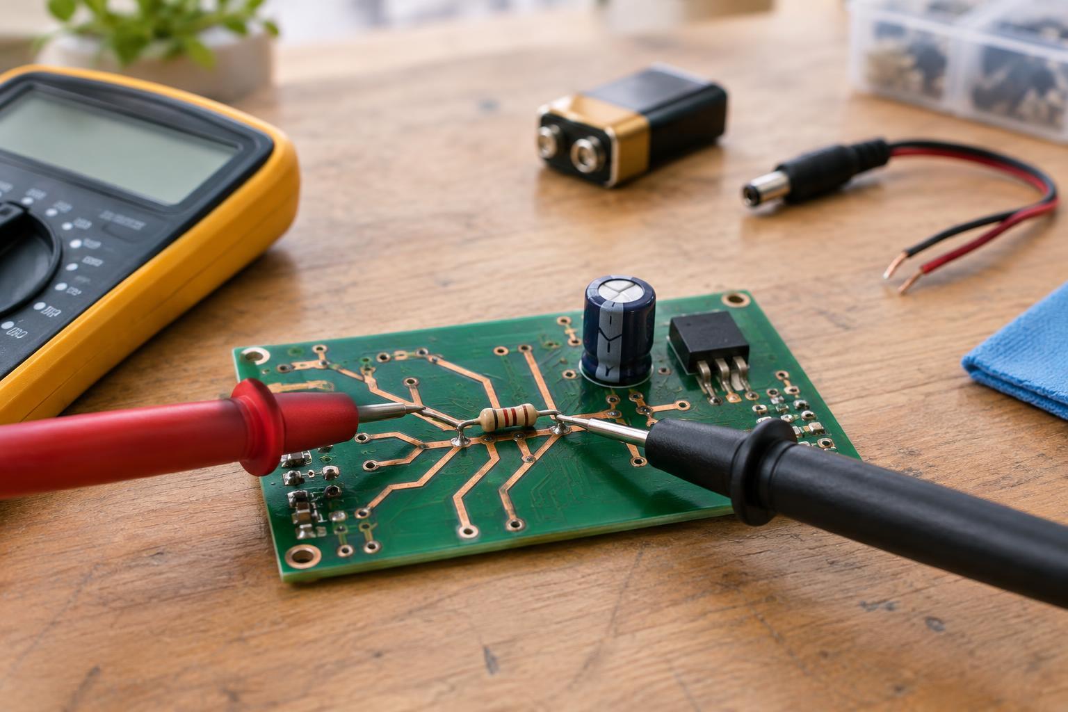
Place one probe on the metal contact at one end of the isolated wire and the other probe on the metal contact at its far end. Touch bare contact surfaces, not plastic housings or wire insulation. A steady beep or low reading suggests the conductor is connected between those points. No beep suggests an open path, but first reposition the probes and confirm that both tips are touching the intended contacts. Oxidation, coatings, and awkward connector shapes can make probe contact unreliable.
If the wire runs through a connector, test the wire and connector in smaller pieces where accessible. For example, compare a reading from the wire end to its connector pin with a reading across the mated connector. This can help distinguish a damaged wire from a poor connector contact. Avoid forcing probes into small terminals, which could spread or damage them.
Narrow down the break
When a wire has several accessible points, keep one probe at a known end and move the other probe along the path. Test at an intermediate terminal or junction, then farther along. If continuity is present up to one point but absent at the next, the open is likely between them. Repeat with closer test points if the construction allows it. This approach works best when you can identify the same conductor throughout the route.
For a long cable, a temporary extension lead can bring one end within reach of the meter. Check the extension lead on its own first, and keep its connections secure. Do not pierce insulation just to create more test points unless you have a suitable method to restore the wire afterward; an unnecessary puncture can become a future failure point.
Interpret the result before making a repair
A beep does not always mean the wire itself is sound. If it is still connected to other parts, a parallel route may complete the test path. Likewise, a damaged wire may pass a gentle continuity test but lose contact when bent or pulled. If you suspect an intermittent break, gently move the cable near strain points while watching the meter, without tugging on terminals or exposing conductors.
Once you have located the likely fault, repair or replace the wire or connector using a method appropriate to the project. Do not bypass fuses or other protective parts to make a continuity test pass. After the repair, repeat the end-to-end test and check that adjacent conductors are not accidentally connected. Only then restore power and test the low-voltage project’s normal operation.