Start with the circuit, not the dial
A multimeter can answer useful first questions: Is a battery providing voltage? Is a switch making contact? Is a wire broken? The setup depends on which question you are asking. This guide is for small, low-voltage circuits such as battery-powered projects and current-limited bench-supply projects. It is not a guide to testing wall outlets, mains-powered equipment, large battery packs, or circuits whose power source you cannot identify.
Low voltage does not automatically mean low risk. A source capable of delivering high current can heat a wire or probe tip during a short circuit. Before testing, identify the power source, turn it off when arranging connections, and keep loose metal objects away. If you are unsure what a circuit contains or whether it is disconnected from mains power, stop rather than probe it.
Check the probe sockets every time
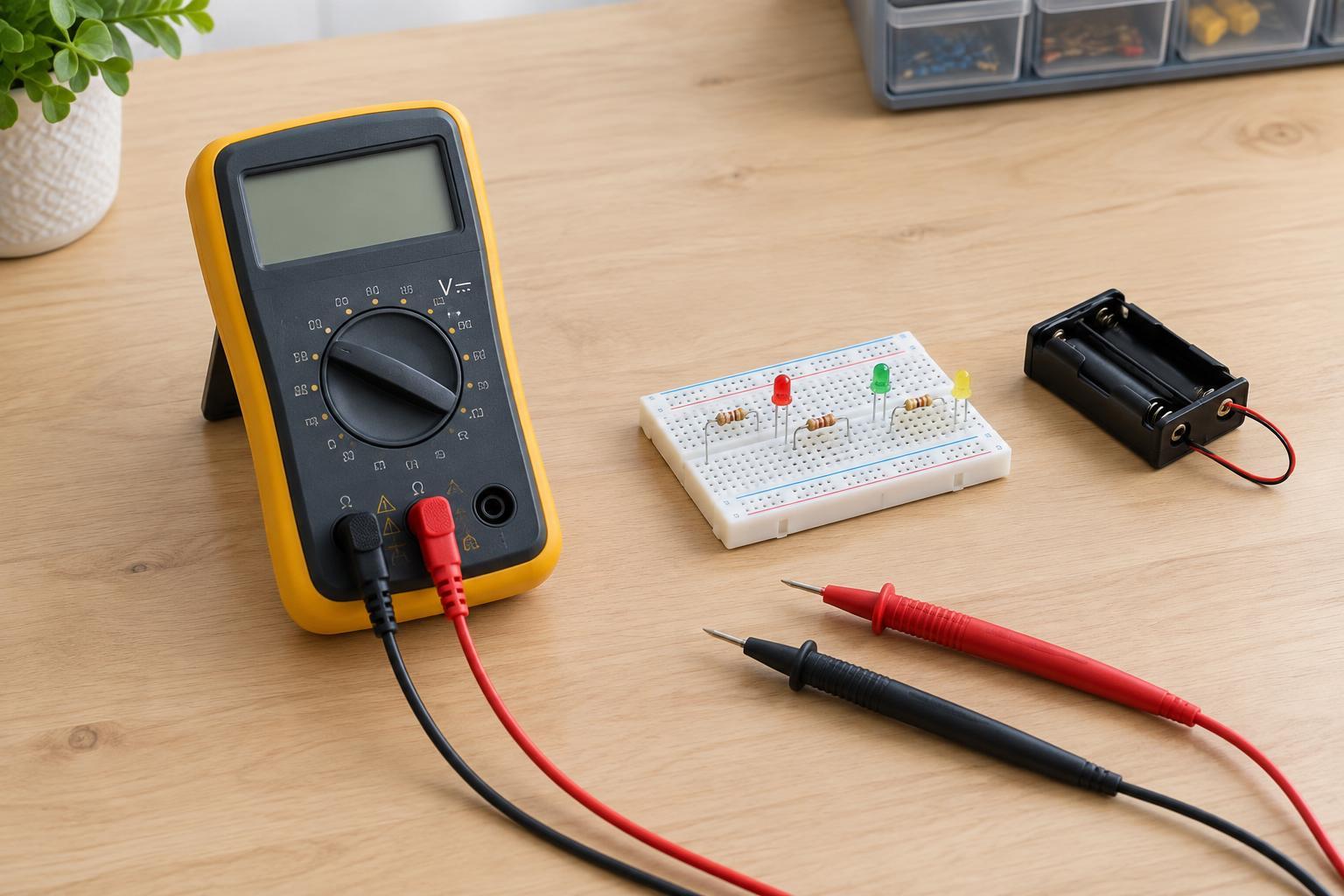
Most meters have a COM socket for the black lead and a V/Ω socket for the red lead when measuring voltage, resistance, or continuity. The exact labels vary, so read the markings on your meter. Some meters also have mA or µA and A sockets for current measurements. These are not interchangeable with the V/Ω socket: they connect to a different measurement path inside the meter.
For ordinary troubleshooting, place the black lead in COM and the red lead in V/Ω before selecting a voltage or resistance function. Check that the leads are fully inserted, their insulation is intact, and the probe tips are not bent or damaged. After any current measurement, move the red lead back to V/Ω. That habit helps prevent a particularly common mistake: trying to measure voltage while the red lead is still in a current socket.
Choose the function and range
Select DC voltage, often marked V with a straight line, for batteries and most small electronic circuits. AC voltage has a different symbol, commonly V with a wavy line. If your meter uses manual ranges and you do not know the expected DC voltage, begin on a range above the circuit’s stated supply voltage, then step down for a more useful reading. An autoranging meter selects the numerical range, but you still need to choose the correct function.
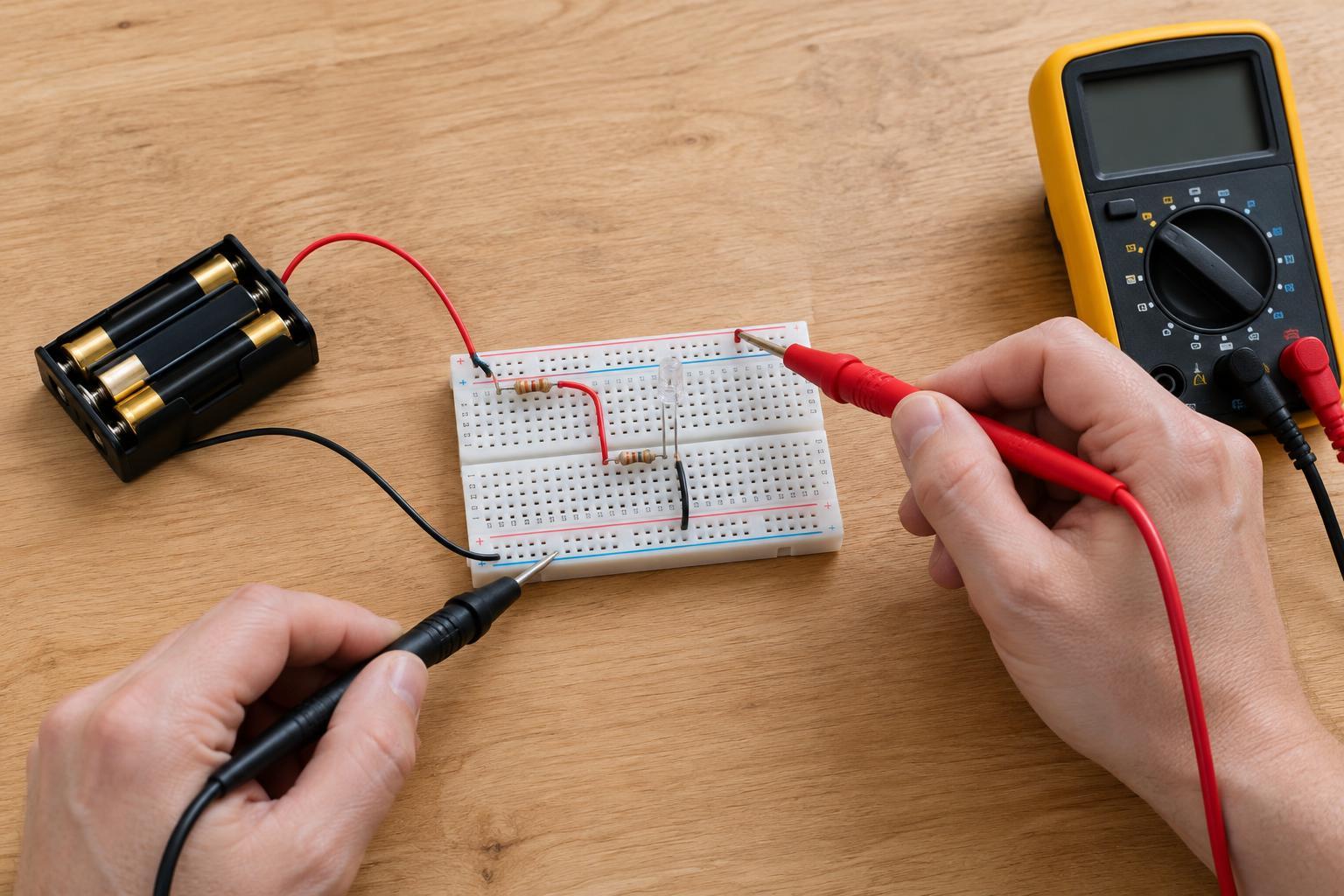
To measure voltage, touch the probes across two points while the circuit is powered: for example, black on the circuit’s ground and red on the point of interest. Keep your fingers behind the probe guards. A negative reading on a DC measurement usually means the probes are reversed relative to the voltage you are measuring. Take care not to let a probe tip bridge adjacent pins or contacts.
Use resistance and continuity only with power off
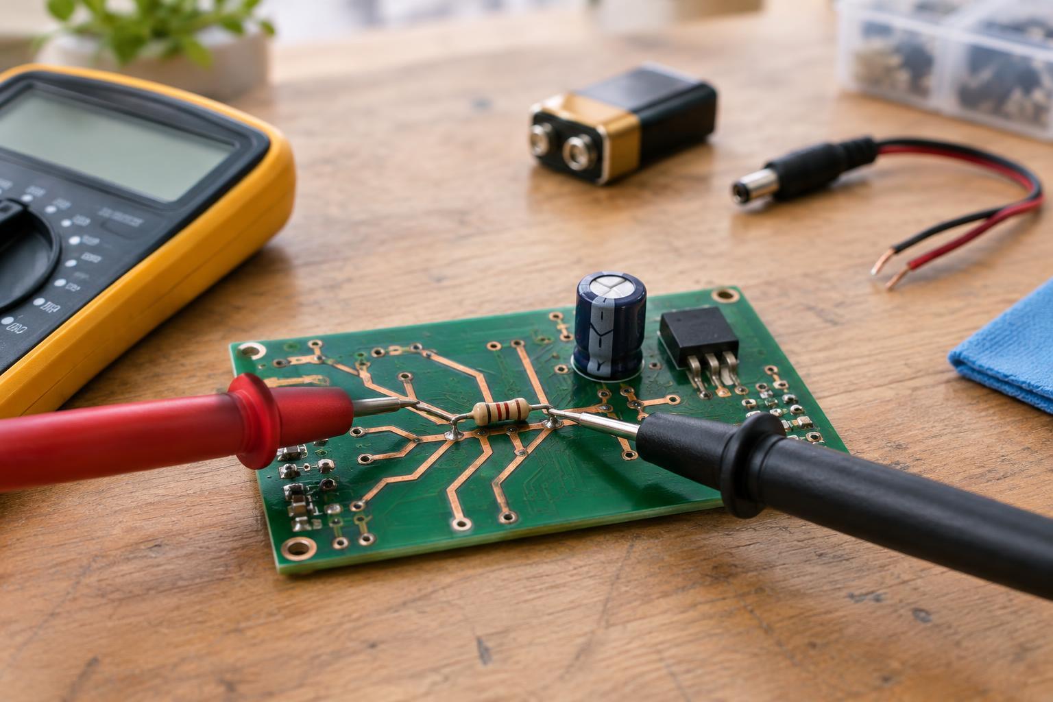
Resistance and continuity modes use the meter’s own small test signal. Disconnect the circuit’s power before using either mode, and allow capacitors to discharge. If you cannot tell whether a capacitor may still hold a charge, do not test that part of the circuit. Touching the probes across a component while it remains connected to other parts can give a misleading reading because current may have another path.
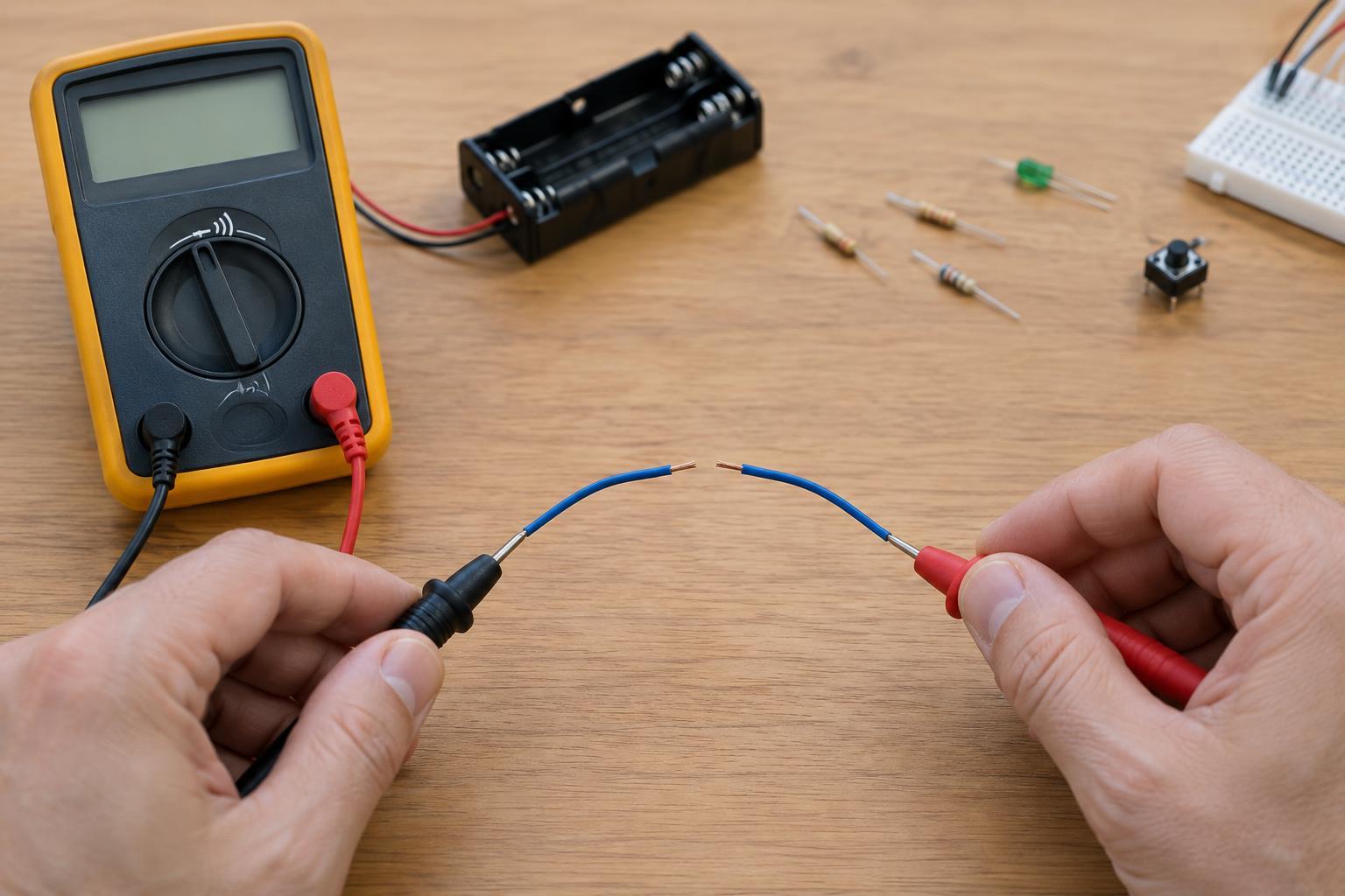
Continuity mode is useful for checking whether two points are connected, such as the ends of a wire or the contacts of a simple switch. A beep generally indicates a low-resistance path, but it does not prove that a connection will work reliably under load. Test a switch in both positions, and compare readings with what its connections are intended to do.
Understand why current measurements need extra care
Voltage is measured across two points; current is measured by opening the circuit and placing the meter in series so current flows through it. Never put probes connected to a current socket directly across a battery, power supply, or component to “check the current.” That can create a short circuit, damage the meter’s fuse, or overheat the leads and source.
If a current measurement is necessary, first turn off the power and consult the meter’s markings and instructions for its socket limits and fuse arrangement. Use a known, current-limited low-voltage source, select an appropriate current setting, and connect the meter in series before restoring power. If the expected current or the correct connection is unclear, use voltage checks and visual inspection instead. When finished, turn power off, remove the meter, restore the circuit connection, and return the red lead to V/Ω.
A brief final check prevents many errors: confirm the lead sockets, dial setting, expected reading, and exact points the probe tips will touch. Taking those few seconds is often more useful than making a hurried measurement.