What these components do
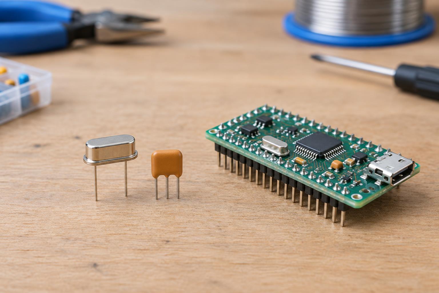
A clock signal gives a digital circuit a regular rhythm. A microcontroller may use it to pace instructions, generate communication timing or measure intervals. Quartz crystals and ceramic resonators are both frequency-selective components that can help an oscillator produce that rhythm. Neither is generally a complete clock generator on its own: it normally works with an oscillator circuit inside a microcontroller or another integrated circuit.
The distinction matters when reading a parts list. A two-pin quartz crystal is not the same thing as a powered oscillator module, which contains circuitry and provides a clock output. Likewise, a ceramic resonator may have two pins or three pins, depending on whether its load capacitors are built in. Before substituting any part, identify what the circuit expects rather than relying on a matching frequency printed on the package.
The main trade-off: timing accuracy
Quartz crystals are usually the better choice when a circuit needs a clock that stays close to its specified frequency. Their frequency can still vary with manufacturing tolerance, temperature, aging and the surrounding circuit, but quartz generally offers better accuracy and stability than a ceramic resonator. This makes a crystal a common choice for timekeeping and for designs whose communication timing has little room for error.
Ceramic resonators are often chosen when lower cost and a simple parts list matter more than precise timing. They can be suitable for a processor clock if the connected devices and software tolerate the resulting frequency variation. That does not mean every crystal-based design needs a resonator upgrade, or that every resonator-based design is inaccurate in practice. The useful question is how much clock error the complete application can accept under its expected operating conditions.
Check the whole oscillator circuit
Frequency alone does not establish compatibility. The integrated circuit must support the type of resonator being used, and the part must suit its oscillator circuit. Relevant specifications can include load capacitance, drive level, equivalent series resistance and the frequency range supported by the clock input. A component that looks like a direct replacement may start slowly, run at the wrong frequency or fail to oscillate if these requirements do not match.
Many crystal circuits use a capacitor from each crystal terminal to ground. Together with stray capacitance from the board and device pins, these capacitors affect the load seen by the crystal and therefore its operating frequency. A three-pin ceramic resonator may already include the capacitors, while a two-pin version may require external ones. Adding capacitors to a part that includes them, or omitting capacitors that the design requires, can cause problems. Follow the integrated circuit’s clock-circuit guidance and the selected component’s specifications.
How to choose for a low-voltage project
Start with the timing requirement, not the component price. If the clock supports an accurate timebase or a demanding data link, check the permitted clock error across the intended conditions. If timing is more forgiving, a ceramic resonator may be adequate. Also consider whether the microcontroller’s internal oscillator already meets the need; an external part adds board space and connections even when it offers an advantage.
For a new design, choose a supported part and use the manufacturer’s recommended layout as a starting point. Keep the resonator and its associated connections close to the oscillator pins, and avoid routing noisy signals alongside them. For a repair, matching the original component’s frequency is only the first step: pin arrangement, capacitor arrangement and electrical specifications matter too. Do not replace a crystal with a resonator simply because the packages fit.
Troubleshooting a clock that will not start
In a low-voltage circuit, begin with checks that do not disturb the oscillator: confirm the supply voltage, the clock configuration and the part orientation or pinout. Inspect solder joints and look for a missing, incorrect or misplaced capacitor. If the circuit worked before a substitution, compare the replacement’s specifications with those of the original. A poor clock connection can resemble a software or processor fault because the processor may not run normally without its expected clock.
Measuring directly at a crystal pin can change the circuit enough to affect oscillation, especially with a probe that adds significant capacitance. If the device provides a buffered clock output or a way to route a clock to a test pin, that may be a more useful measurement point. Keep this work to low-voltage, accessible circuits within your skill level; do not probe an exposed mains-powered board to investigate a clock fault.