What changes when you turn the shaft?
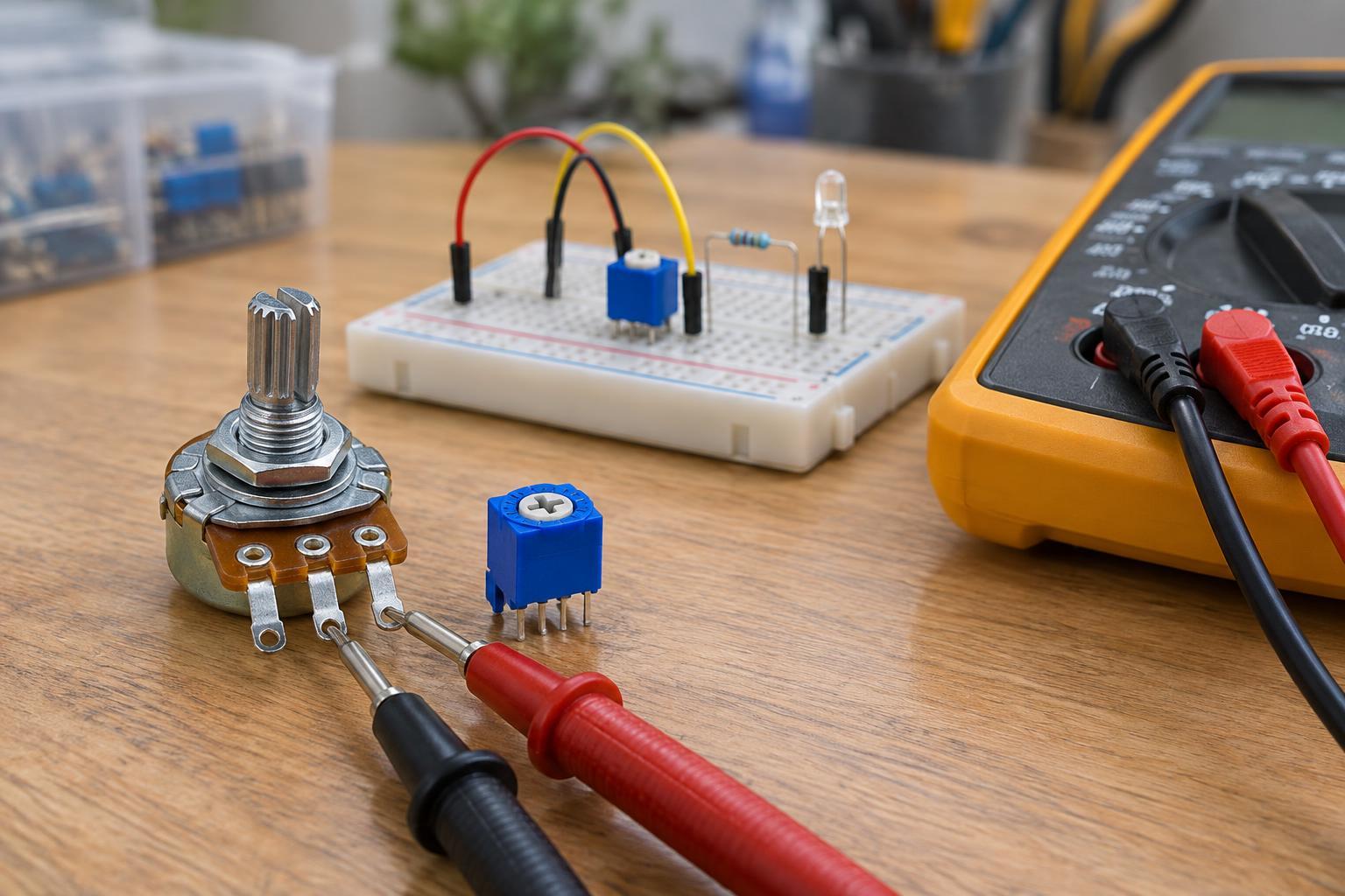
A potentiometer contains a resistive track and a movable contact called a wiper. Its two outer terminals connect to the ends of the track; the middle terminal usually connects to the wiper. Turning the shaft changes the resistance between the wiper and each outer terminal. The resistance between the two outer terminals stays approximately constant and is the part’s nominal value, such as 10 kΩ.
A trimmer works on the same principle but is intended for occasional adjustment, often with a small screwdriver. A panel-mounted potentiometer suits a control someone will use regularly, while a trimmer suits a setting made during assembly or calibration. Some trimmers take several turns to travel from one end of the track to the other, making small adjustments easier.
Choose a resistance range for the circuit
The printed value describes the total resistance between the outer terminals, not the range between the wiper and one end. On a nominal 10 kΩ potentiometer, the wiper-to-end resistance can move from near zero to near 10 kΩ. Real parts have tolerances and may retain a little resistance at the ends of travel.
For a low-voltage voltage divider feeding a high-impedance input, values such as 10 kΩ and 100 kΩ can both be useful, but they involve trade-offs. A lower resistance draws more current between the supply rails. A higher resistance draws less current but makes the wiper signal more sensitive to electrical noise, leakage, and any load connected to it. Check the requirements of the input circuit rather than assuming one value works everywhere.
Power rating matters too. A resistive track can overheat if too much voltage is applied across it or if a section must carry too much current. Check the part’s voltage and power ratings, especially when using it as a variable resistor. Keep beginner experiments on an appropriately limited, low-voltage supply; do not connect a small potentiometer or trimmer directly to mains wiring.
Understand linear and audio tapers
Taper describes how wiper position relates to resistance. A linear potentiometer changes resistance at a roughly steady rate as the shaft turns. It is often a straightforward choice for setting a reference voltage or adjusting a parameter where you want predictable travel. A nominal 10 kΩ linear part will have roughly half its total resistance on each side of the wiper near the middle of its travel, subject to tolerance.
An audio, or logarithmic, taper changes resistance unevenly across the rotation. It can make a manual volume control feel more gradual to a listener than a linear part would. Reverse-audio tapers also exist. Markings such as A and B may indicate taper, but conventions can vary by manufacturer or region. If the taper matters, check the part’s documentation or measure several positions rather than relying on a letter alone.
Connect the three terminals deliberately
To use a potentiometer as a voltage divider, connect the two outer terminals across the low-voltage source and take the adjustable output from the wiper. For example, with one end at 0 V and the other at 3.3 V, the wiper can provide an intermediate voltage. Reversing the two outer connections reverses which turning direction raises the output. A load on the wiper can change the expected voltage, so a divider is best suited to an input that draws little current.
To use it as a variable resistor, connect the wiper and one outer terminal. The resistance between those connections changes as you turn the shaft. In some designs, the unused outer terminal is tied to the wiper so a momentary loss of wiper contact is less likely to leave the circuit open. That connection does not make an unsuitable current or power rating safe. Also check the resistance at both ends of travel: a near-zero setting may require a separate fixed resistor to keep current within safe limits.
Verify the part before installing it
With power disconnected and the component isolated from the circuit, use a multimeter in resistance mode to find the pair of terminals whose reading remains nearly constant while you turn the shaft. Those are the ends of the track. Measure between the remaining terminal and each end as you turn: one reading should generally rise while the other falls. This check can also reveal a scratchy or intermittent wiper, though readings can be less steady while the shaft is moving.
Before soldering, confirm the intended turning direction, available mounting space, and whether the control needs frequent access. For a trimmer, start near the middle of its travel when practical, then adjust only within the circuit’s safe operating range. These small checks prevent a common mistake: choosing the right resistance value but wiring a control that behaves backward, loads the circuit unexpectedly, or reaches an unsafe setting.