What the two signals tell you
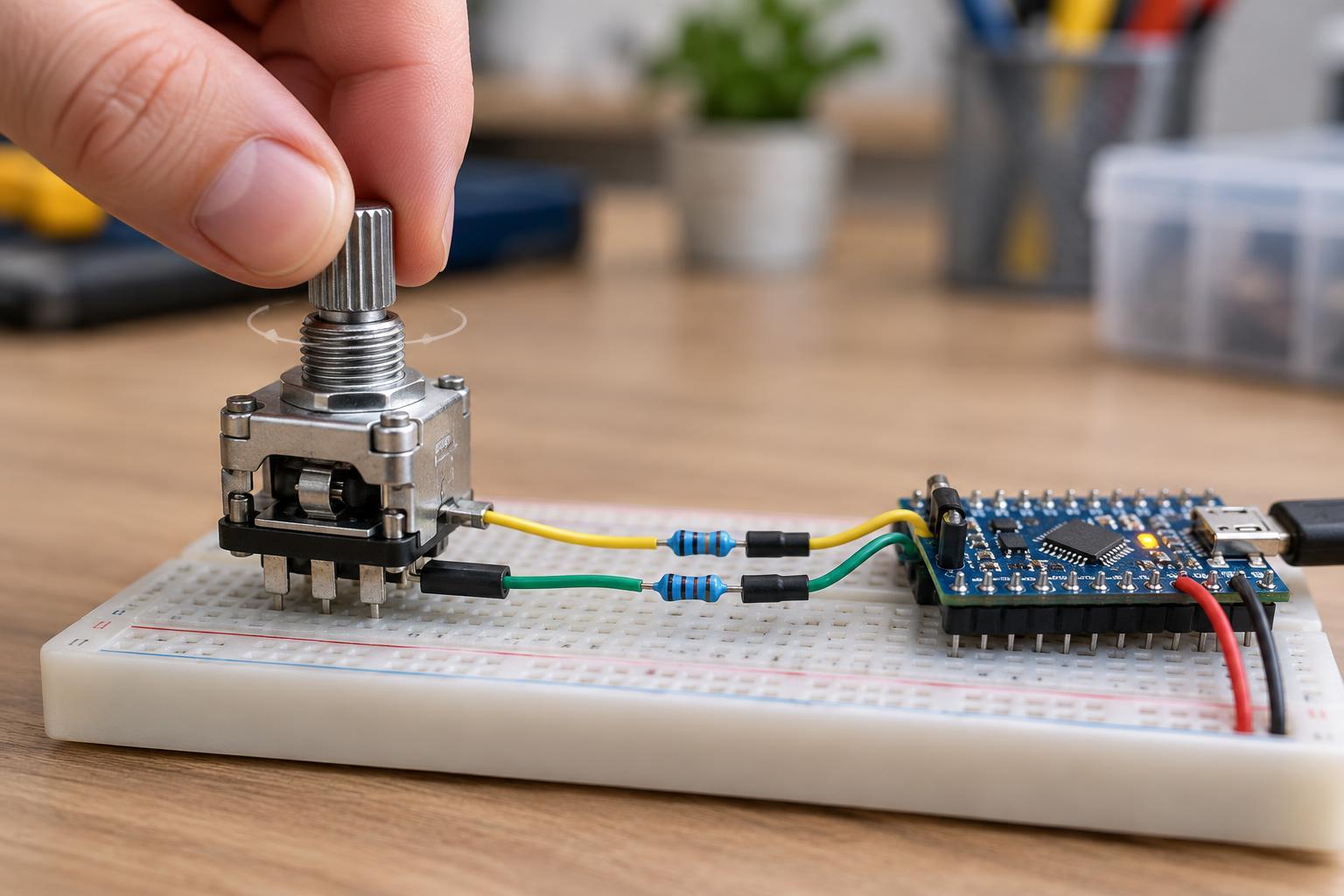
A quadrature rotary encoder has two outputs, usually called A and B. As the shaft turns, their high and low states change in a repeating sequence. One possible sequence is 00, 01, 11, 10, then back to 00, where each pair represents the current A and B levels. Turning the other way reverses that order. Because only one bit should change at a time, a controller can use each transition to determine direction as well as movement.
There is no universal rule that “A first” means clockwise. It depends on the encoder’s wiring, how the outputs are named, and which side you view the shaft from. After connecting an encoder, turn it slowly in the direction you want to call positive and check the reported sign. If it is reversed, swap A and B in the wiring or change the sign in software.
An encoder reports changes in position, not an absolute shaft angle. Unless the device has a separate index or another position reference, a controller that starts up cannot know how many turns occurred while it was off. For a menu knob, this is usually fine: the application needs to know which way the user turned and by how much.
Connect the encoder for clean, compatible signals
Many hand-operated mechanical encoders contain switches that connect A or B to a common terminal. These contacts need pull-up resistors so an open contact reads high and a closed contact reads low. A microcontroller’s internal pull-ups may be suitable for a short, simple connection, though the appropriate choice depends on its input specifications and the encoder. Connect the encoder common to the controller ground, and keep wiring reasonably short to reduce noise pickup.
Not every quadrature encoder uses bare contacts. Optical and magnetic models may provide electronic outputs that need power and may be push-pull or open-drain. Check the device’s pinout, supply range, and output type before connecting it. In particular, an output at a higher voltage may not be safe for a lower-voltage microcontroller input. These are low-voltage signal connections; do not connect an encoder or development board directly to mains wiring.
Count transitions, not assumptions about clicks
A full A/B sequence contains four valid transitions, but a physical detent—the position where a knob clicks—does not always correspond to one full sequence. On some encoders, a detent occurs at every sequence; on others, it occurs at different points. A counter that assumes four transitions per click may therefore appear to skip clicks or count several times per click even when it reads every signal correctly.
Start by recording the A/B states while turning the shaft slowly through several detents. Note which states repeat at each resting position, then choose what the application should count: every valid transition, a complete four-transition cycle, or movement between detents. Counting every transition gives finer resolution but may be too sensitive for a menu. Counting completed cycles can make a hand-operated control feel steadier, provided it matches the encoder.
Handle bounce without hiding real movement
Mechanical contacts can bounce as they open or close, producing rapid changes that do not represent deliberate rotation. A useful decoder remembers the previous two-bit state and accepts only neighboring states in the quadrature sequence. It adds or subtracts one for a valid transition and ignores an apparent jump in which both bits change at once. This state-based approach is generally more reliable than counting edges on A alone and reading B once for direction.
Bounce can still produce a series of valid-looking transitions forward and backward. For a hand-operated knob, accumulating transitions and reporting a step only after the expected sequence is complete can reduce false output. Modest hardware or software filtering may also help, but an aggressive delay can conceal genuine transitions when the shaft turns quickly. Test the control at both slow and fast speeds rather than choosing a debounce interval solely by how it behaves at rest.
Keep the reader fast enough
Even a good decoder cannot recover transitions it never observes. A polling loop that spends too long updating a display, waiting for input, or performing other blocking work may see the same state twice after the shaft has moved through intermediate states. Poll both inputs frequently and keep the sampling interval short relative to the fastest expected transitions. For faster encoders or busier applications, pin-change interrupts or a controller’s dedicated encoder peripheral may be more suitable.
When using interrupts, read A and B together as one state, update a small counter, and leave lengthy work for the main program. Share that counter safely between interrupt and main code according to the controller’s rules; on some devices, reading a multi-byte value requires protection against an update halfway through. If counts remain inconsistent, check the wiring and voltage levels first, then inspect the observed state sequence. Distinguishing noisy signals, misunderstood detents, and missed samples makes troubleshooting much easier.