What an op-amp does
An operational amplifier, or op-amp, has two signal inputs and an output. It responds to the difference between the non-inverting input, marked +, and the inverting input, marked −. If the + input is higher than the − input, the output tends to move upward; if it is lower, the output tends to move downward. The op-amp also needs power connections, called supply rails. These power connections are separate from the two signal inputs.
An op-amp’s internal gain is very large, so even a small difference between its inputs can drive its output toward a limit. Most useful amplifier circuits therefore connect some of the output back to the − input. This negative feedback helps set a predictable gain and keeps the circuit operating between its output limits. The idea that feedback makes the inputs nearly equal is useful, but only while the op-amp is operating within its specified ranges.
Supply rails set the operating boundaries
The supply rails provide the power that lets an op-amp produce an output. A dual-supply circuit might have one rail above ground and another below it. A single-supply circuit has a positive rail and a lower rail that is often ground. In both cases, voltages are measured relative to a chosen reference; ground is not a special requirement of the op-amp itself.
An op-amp powered from a single positive supply generally cannot produce a negative output voltage. It also cannot produce an output higher than its positive supply through normal operation. Some designs place their signal around a midpoint reference so that a changing waveform has room to move both up and down without needing a negative supply. That midpoint is a signal reference, not a new source of power.
Before connecting a device, check its specified supply-voltage range and pinout. Op-amps with similar-looking names or packages need not share the same pin assignments or operating limits. On a low-voltage breadboard, a small bypass capacitor near the supply pins is often helpful for keeping the supply steady as the circuit operates.
The inputs have a usable range
The two inputs sense voltage, but they cannot necessarily accept every voltage between the supply rails and still behave as expected. A specification called the input common-mode voltage range describes where the input voltages may sit for normal operation. If an input goes outside that range, the output may no longer follow the simple rules used to analyze the circuit. A voltage can therefore be safe for the device yet still be outside its usable measurement range; consult the datasheet for both operating and absolute limits.
A description such as “rail-to-rail input” suggests that the usable input range extends close to both rails, but it does not replace the actual specifications. The allowable range can depend on the supply voltage and the particular part. For example, a single-supply sensor circuit intended to measure a signal near ground needs an op-amp whose input range includes that region. Feedback cannot correct an input-range limitation.
The output has limits too
An output cannot always swing all the way to either rail. How close it can get depends on the op-amp, its supply voltage, and the load connected to the output. “Rail-to-rail output” means the output is designed to approach the rails under stated conditions, not that it will equal them for every load. If a circuit asks for an output beyond the available swing, the output reaches a limit and the intended gain no longer applies. This is often called saturation or clipping.
The output also has a limited ability to supply or absorb current. A load that draws too much current can prevent the output from reaching its expected voltage or strain the device. When an amplifier works with a light measuring load but not with an LED, speaker, or other demanding load, check the output-current specifications rather than assuming the gain calculation is wrong. An op-amp is not automatically a suitable power driver.
A practical way to check a low-voltage design
Start with the proposed supply and identify both rail voltages. Next, estimate the lowest and highest voltages expected at each input, including any midpoint reference. Compare those values with the op-amp’s input common-mode range. Then calculate the output range the feedback circuit requests and compare it with the specified output swing under the intended load. These checks help identify a mismatch before a circuit is assembled.
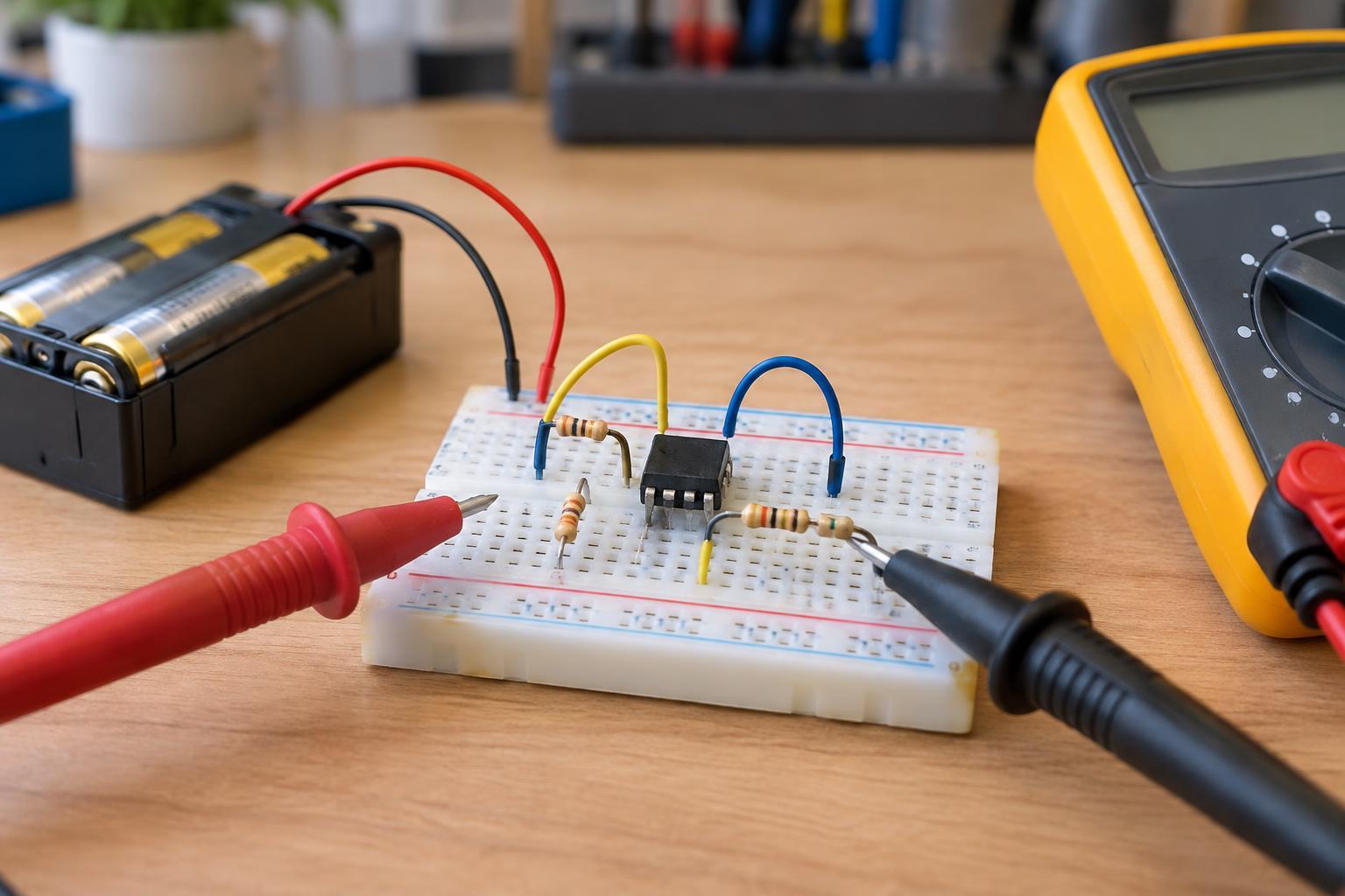
For a first test, use a current-limited, low-voltage supply and a simple load within the part’s ratings. With power off, verify the pinout and wiring. After powering the circuit, measure the rails and the input and output voltages relative to the same reference. If the output is stuck near a rail, check the supply, input range, feedback path, requested output swing, and load. Keep beginner op-amp experiments on isolated low-voltage supplies; do not connect a breadboard circuit directly to mains wiring.