What an ADC IC measures
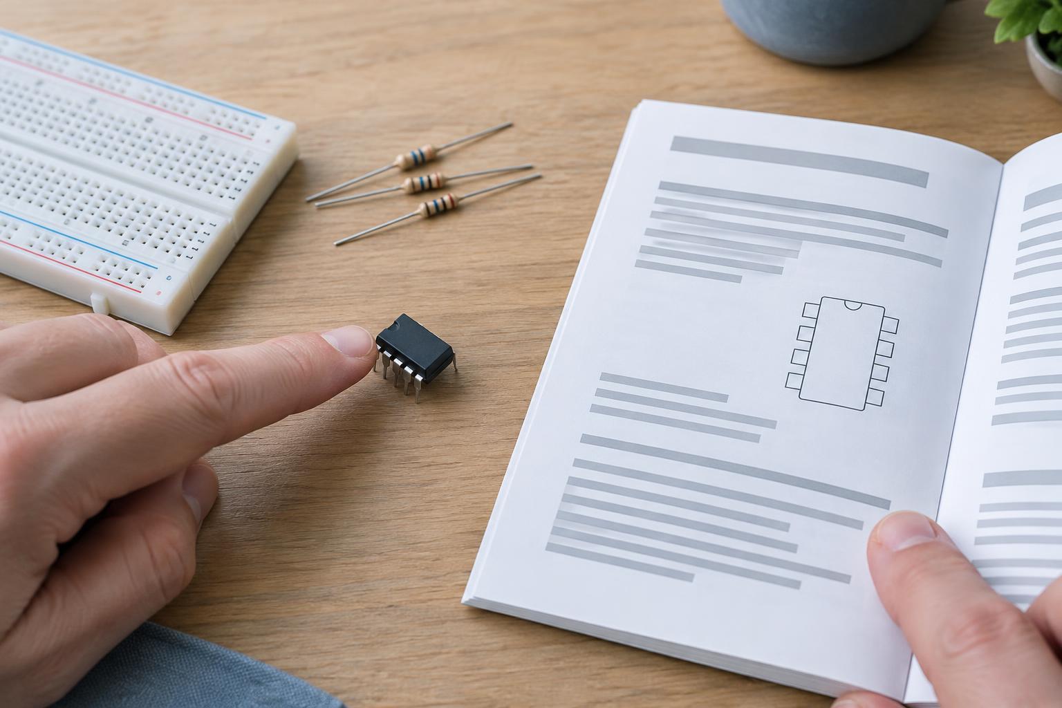
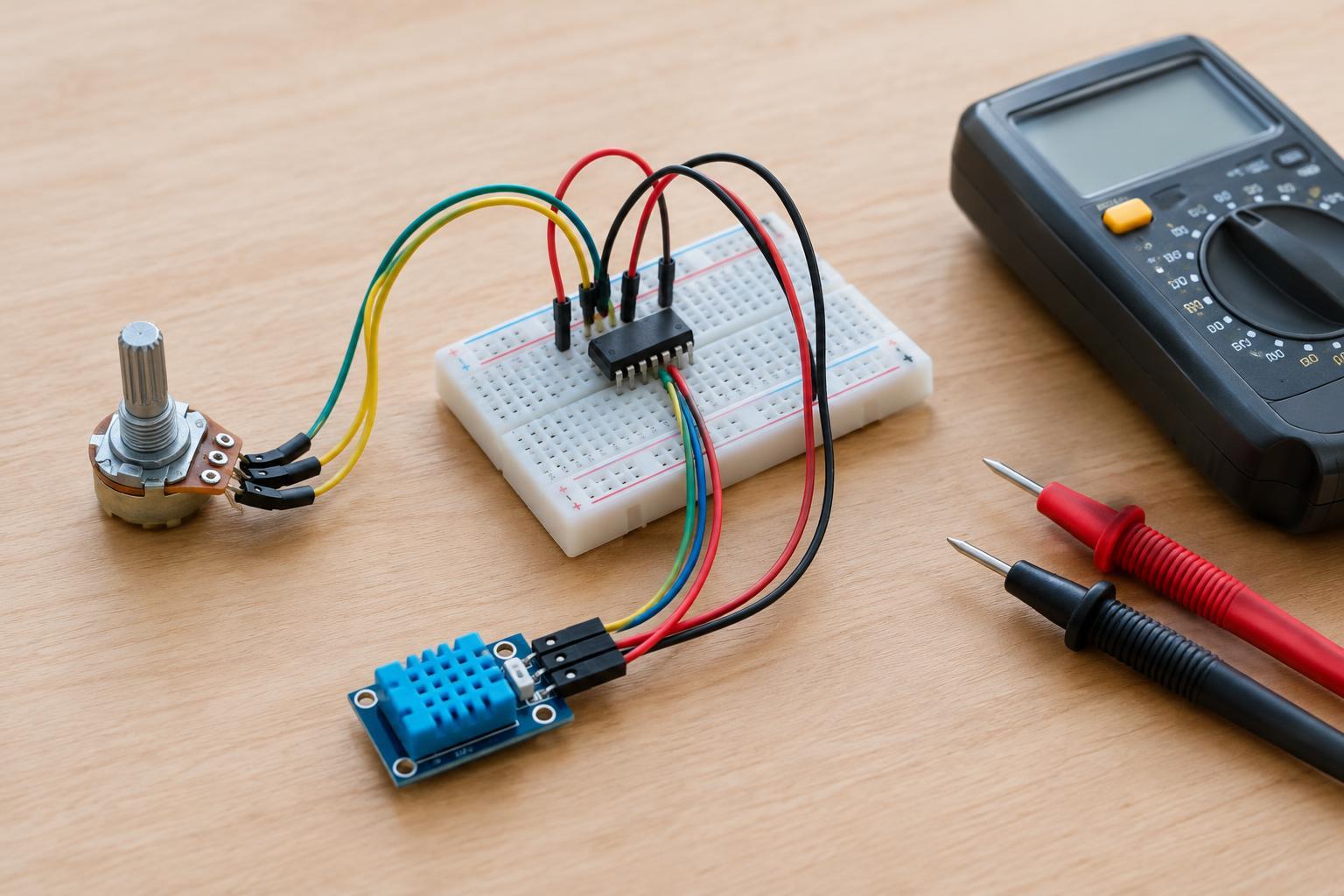
An analog-to-digital converter, or ADC, measures an electrical input and reports a digital code. It gives a microcontroller a way to read signals such as a sensor’s output voltage or the voltage across a low-voltage battery. Some microcontrollers contain an ADC; a separate ADC IC can be useful when a project needs a different channel count, interface, input arrangement, or measurement capability.
The code is not a voltage by itself. To interpret it, you need to know the converter’s resolution, its reference voltage, and the input range selected for that channel. Those details are specific to the IC and its configuration, so a code-to-voltage calculation that works for one setup may be wrong for another.
Resolution sets the size of each step
Resolution is commonly stated in bits. An N-bit ADC can produce 2^N distinct codes: for example, a 10-bit converter has 1,024 codes, usually numbered 0 through 1,023. If its specified measurement span is 0 to 3.3 V, one ideal code step is approximately 3.3 V divided by 1,024, or 3.22 mV. This step is often called the least significant bit, or LSB.
Smaller steps let the converter distinguish smaller changes under suitable conditions, but more bits do not automatically make a reading more accurate. Noise, reference drift, input errors, and the ADC’s own imperfections can all affect the result. Nor should you assume that a full-scale input maps neatly to the highest code in every calculation: endpoint behavior and transfer formulas vary by device. Use the datasheet’s definitions when converting codes into reported voltages.
The reference gives the codes meaning
The reference voltage establishes the scale against which an ADC compares its input. In a simple unipolar arrangement that measures from zero to the reference, increasing the reference widens the voltage span represented by the available codes. With the same bit count, that also makes each ideal step larger. Lowering the reference makes each step smaller, but only if the signal remains inside the permitted input range.
An ADC may use an internal reference, an external reference IC, or a supply-derived reference, depending on its design. The right choice depends on what you want the reading to mean. If you need to compare a sensor voltage with a known voltage scale, reference stability matters. If both the sensor output and ADC reference change in proportion to the same supply, their ratio may matter more than that supply’s exact voltage. Check the device’s reference requirements before connecting one; reference pins are not interchangeable with ordinary input pins.
Input range is more than a single voltage limit
The input range is the span the ADC is designed to convert, and it may be narrower than the voltages the IC can tolerate without damage. A single-ended channel typically measures an input relative to a shared ground. A differential channel measures the difference between two inputs, but each pin may still have to remain within its own allowed voltage limits. Some converters offer selectable ranges or can represent positive and negative differences; others cannot.
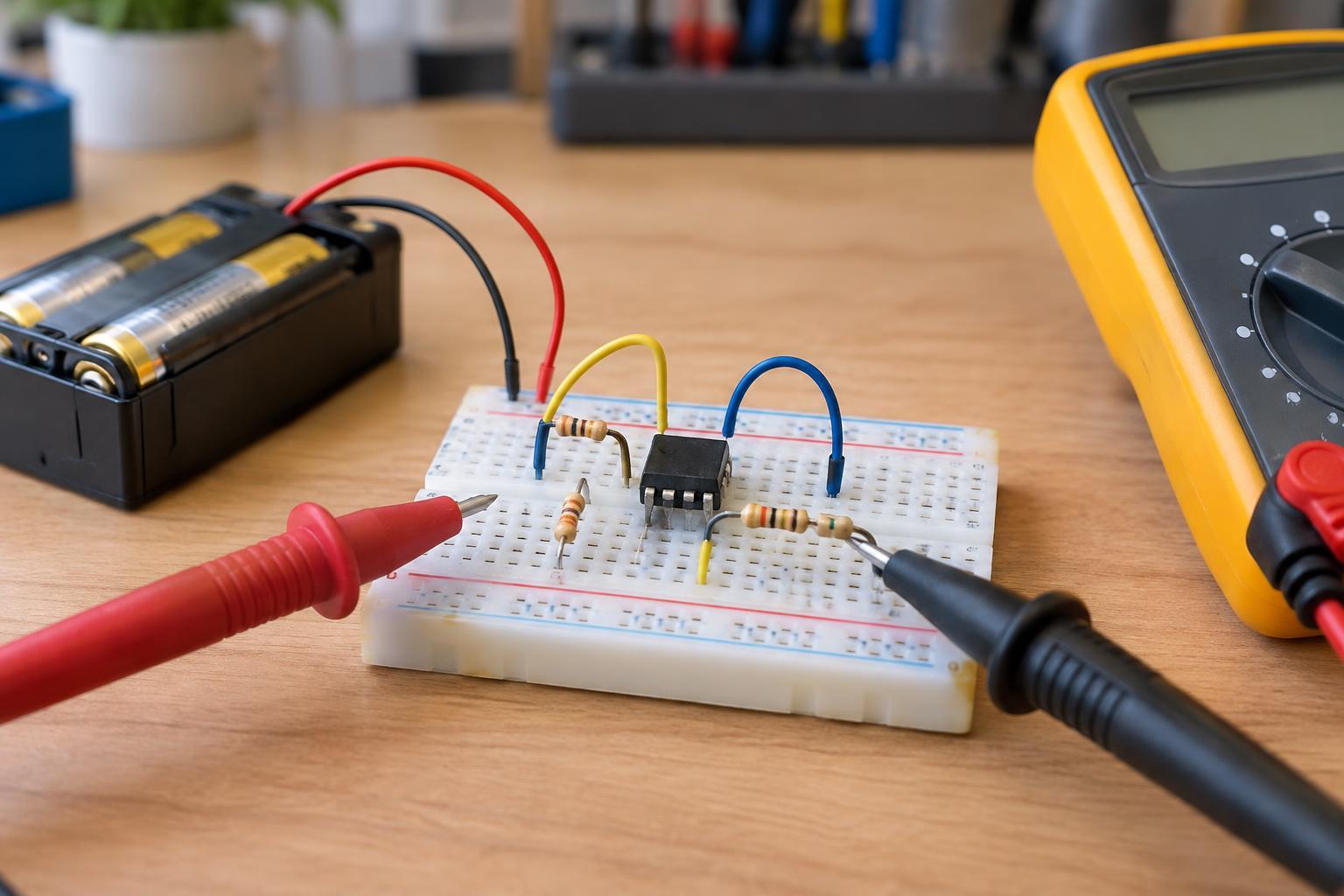
A reading outside the conversion range may clip at the lowest or highest code rather than reveal how far outside the range the signal is. More importantly, exceeding a pin’s absolute maximum rating can damage the IC. Before wiring a sensor, check both the specified conversion range and the limits for each input pin, taking the supply voltage and reference configuration into account. A resistor divider can reduce a higher low-voltage signal, but its output and any expected transients must still stay within the ADC’s limits.
Putting the three specifications together
Start with the sensor’s expected minimum and maximum output. Choose an ADC configuration whose input range covers that span, including reasonable variation. Then consider whether the ideal step size is small enough for the changes you need to observe. If only a small part of the range is used, many available codes go unused; a suitable range or reference setting may improve useful resolution, provided the IC supports it.
Finally, check the conditions behind the advertised bit count. Some ADC inputs briefly draw charge when sampling, so a high-impedance sensor or large series resistor may need more acquisition time or a suitable buffer circuit. Follow the datasheet’s guidance for input drive, grounding, supply decoupling, and reference connections. For a first test, use a known, safely limited low-voltage source and compare readings near the bottom, middle, and top of the intended range. Keep maker projects isolated from mains wiring and other hazardous voltages; an ADC input is a measurement pin, not a safety barrier.