What the divider needs to do
A three-AA battery pack can provide more voltage than a 3.3 V analog-to-digital converter (ADC) pin is allowed to receive. A voltage divider reduces the pack voltage to a fraction that the ADC can measure. This example is for a three-cell holder containing AA alkaline cells or AA NiMH rechargeable cells. It is not a design for lithium cells, mains-powered equipment, or an unidentified battery pack.
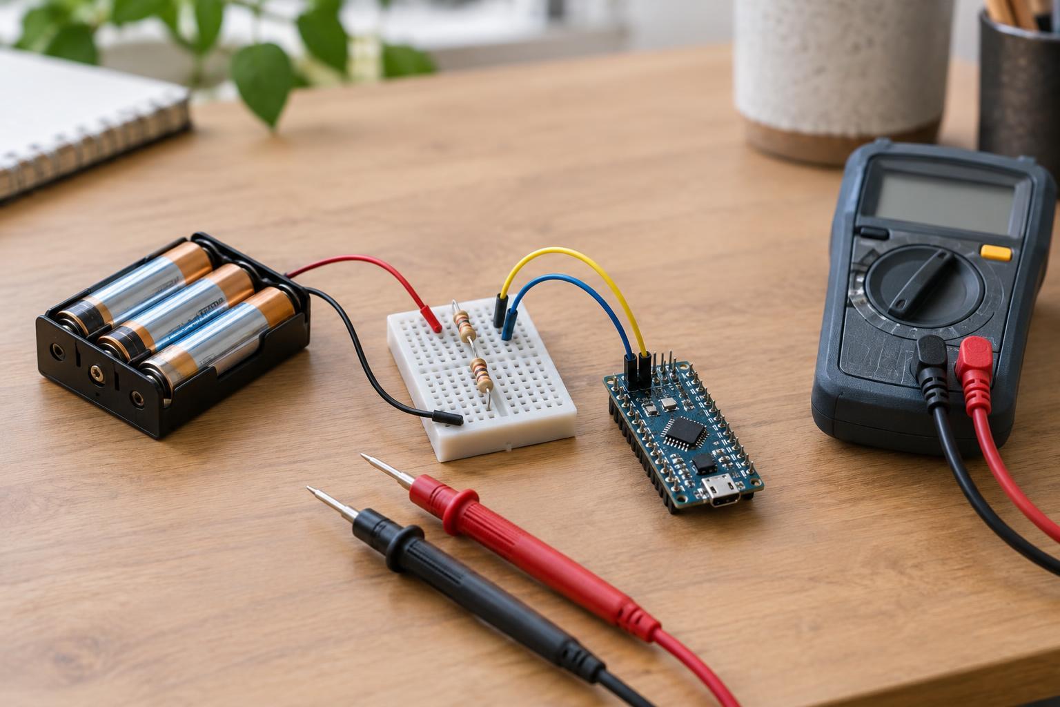
Use two 10 kΩ resistors in series. Connect the top resistor from battery positive to the measurement junction, and the bottom resistor from that junction to battery negative. Connect the ADC input to the junction. With equal resistor values, the junction sits at approximately half the pack voltage: a 4.8 V pack, for example, produces about 2.4 V at the ADC input. The microcontroller ground and battery negative must share a connection for the reading to have meaning.
Check the voltage limits for your particular board before wiring it. A nominally 3.3 V ADC pin is not necessarily tolerant of 3.3 V when the board is unpowered, and some boards have additional restrictions. Connect and disconnect the pack with the board switched off, verify polarity, and do not assume the divider protects against a reversed battery or a wiring error. This project stays at low battery voltages; do not connect the circuit to a wall outlet or other unknown supply.
Build and check the circuit
Place the two resistors on a breadboard so that they meet at one junction. Run one wire from pack positive to the free end of the top resistor, another from the free end of the bottom resistor to pack negative, and a third from the junction to an ADC-capable pin. Link pack negative to the board’s ground. Keep the battery pack out of the circuit until you have checked that no wire bypasses a resistor or connects pack positive directly to the ADC pin.
The two 10 kΩ resistors draw current whenever the pack is connected, even when the microcontroller is not taking readings. At 4.8 V, that current is about 0.24 mA. That may be acceptable for a short experiment but can matter in a device left connected for a long time. A switched measurement circuit can reduce the drain, although its switch and timing need their own design checks.
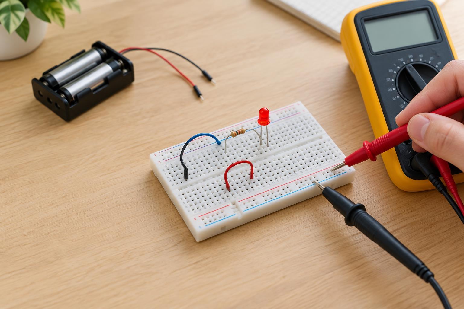
Before attaching the ADC wire, you can check the divider junction with a multimeter. Measure between the junction and pack negative; it should be close to half the voltage measured across the entire pack. If the reading is unexpectedly high, negative, or unstable, disconnect the pack and recheck the wiring. A small ceramic capacitor, such as 10 nF to 100 nF, between the junction and ground may help steady noisy readings, but allow the reading to settle after a connection or switching event.
Convert an ADC reading to pack voltage
For a 12-bit ADC that reports values from 0 to 4095, a useful first approximation is: pack voltage = ADC reading ÷ 4095 × ADC reference voltage × 2. The final factor of two reverses the effect of the equal-resistor divider. If the reference is 3.3 V and the reading is about 2978, the estimate is about 4.8 V. Substitute your ADC’s actual resolution and reference voltage; neither should be guessed from a board’s supply label if accuracy matters.
Resistor tolerances, reference-voltage variation, ADC behavior, and wiring can all affect the result. For a better estimate, use the actual resistor values in place of the factor of two: multiply the measured junction voltage by the sum of the top and bottom resistances, then divide by the bottom resistance. Check your ADC documentation for its recommended source impedance and sampling settings. If readings jump around, take several samples and average them only after checking for a loose connection or a changing supply.
Use the reading as an indication, not a fuel gauge
Pack voltage is useful for spotting broad changes and for warning that a device may soon stop working. It does not directly tell you how much energy remains. Voltage changes with cell chemistry, load, temperature, and how long the cells have rested. A reading taken while a motor runs may differ from one taken after the motor stops, so compare readings made under similar conditions.
If the pack also powers the microcontroller through a 3.3 V regulator, measurement may stop or become unreliable once the pack falls below the regulator’s required input voltage. Plan any low-battery indication to happen while the board still operates normally. Avoid mixing cell types or old and new cells in the holder, and remove cells from a project that will be stored. The most valuable result from this circuit is a repeatable voltage trend, interpreted with the limits of the battery and ADC in mind.