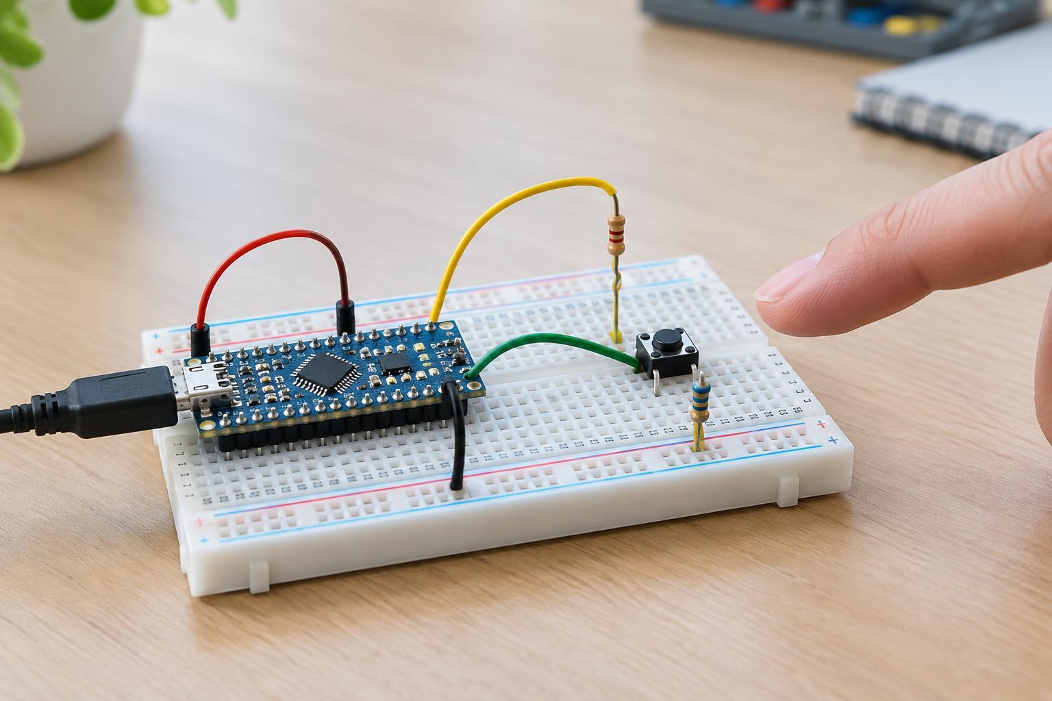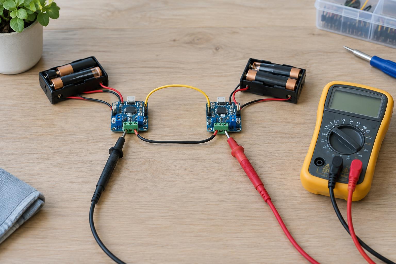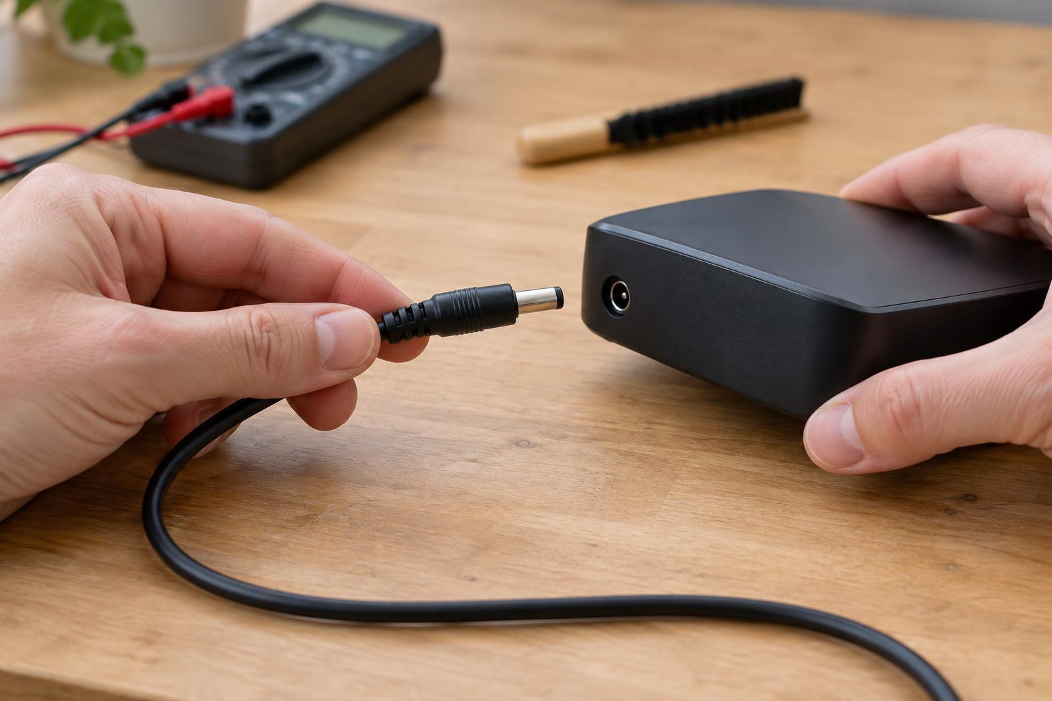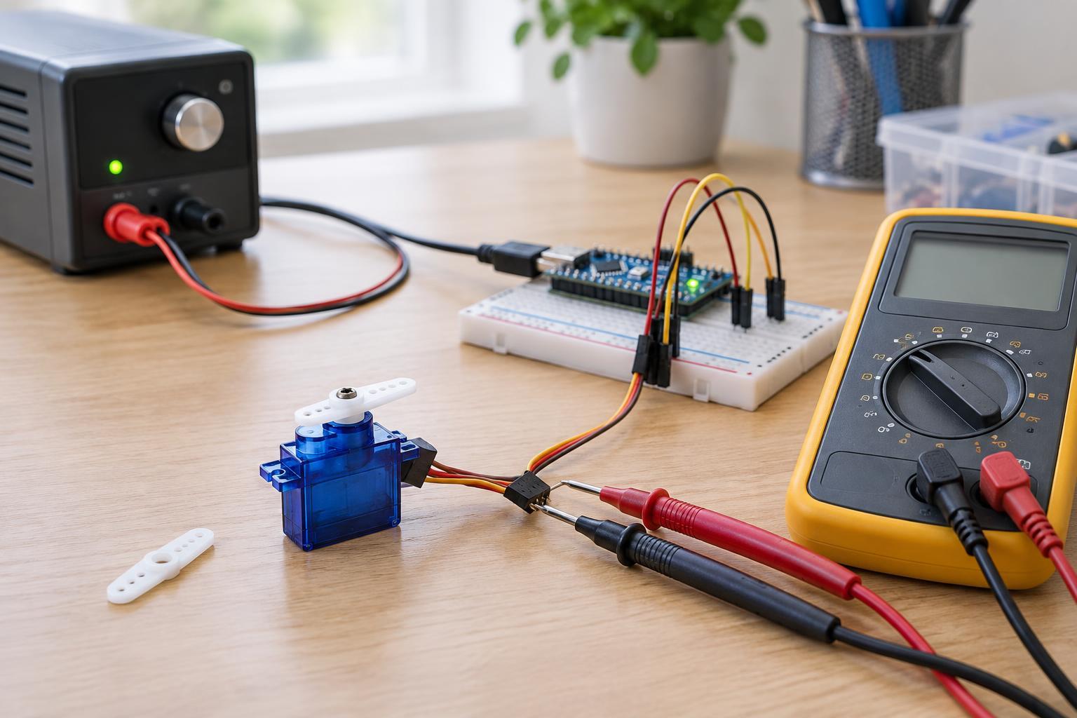
Start with a safe, simple test
A hobby servo moves toward a position requested by its control signal. A small amount of movement near that position can be normal, but repeated twitching, buzzing or unpredictable jumps are worth investigating. The cause is not always the servo itself: power delivery, wiring, signal timing and mechanical load can produce similar symptoms.
Before changing connections, turn off power and check the servo’s labeled voltage range and wire identification. Do not assume every cable uses the same colors or pin order. Keep this test on a suitable low-voltage supply; do not open a mains-powered supply or probe inside equipment connected to mains power. If the servo becomes unusually hot, smells damaged or stalls hard against a stop, disconnect it and investigate before trying again.
For a first test, remove any attached arm or linkage if it can be removed safely. Command a position near the middle of travel rather than an extreme. This reduces mechanical load and helps separate an electrical problem from a mechanism that is binding.
Check the supply voltage where the servo uses it
Servos can draw much more current while starting, changing direction or pushing a load than while sitting still. A supply that appears adequate when idle may dip during movement. If the voltage falls far enough, the servo may lose position or the controller may restart, making the motion look like a signal problem.
Confirm that the supply voltage suits the servo and that the supply can handle its expected load. If you have a multimeter and can measure without risking a short, check voltage across the servo’s power and ground connections while it moves. A reading at the supply terminals alone may miss a drop along thin wires, loose connectors or a breadboard power path. A basic meter may not capture very brief dips, so a steady reading does not rule them out completely.
If the servo is powered from a controller board or USB connection, check that the path is intended to supply servo current. When using a separate regulated low-voltage supply for the servo, do not join the two supplies’ positive outputs unless the equipment documentation specifically calls for it. A capacitor near the servo may help with brief disturbances in an appropriate circuit, but it is not a substitute for a suitable supply. Observe its polarity and voltage rating.
Make sure ground and connectors are reliable
The controller and servo need a shared ground reference so the servo can interpret the control signal correctly. With power off, trace the wiring: the servo’s ground should connect to the controller’s ground, even when the servo has a separate low-voltage power supply. The servo’s positive power lead should connect only to its intended supply, and its signal lead should connect to the intended controller output.
Reseat connectors and inspect for bent pins, frayed wires and intermittent contacts. Gently moving a cable while the system runs may reveal a loose connection, but keep fingers and tools clear of moving parts and exposed conductors. Long or poorly secured leads can make a setup less reliable. Shortening a temporary test setup and securing its connections can help establish whether the wiring is involved.
Check the control signal, then the load
A typical positional hobby servo expects a repeating control pulse whose width represents the requested position. Many setups use pulses roughly 1 to 2 milliseconds wide, repeated about every 20 milliseconds, but supported timing and travel limits vary by servo. Use the servo’s specifications and a known working example for your controller rather than assuming that one set of values fits every model. This control pulse is not the same as simply varying the duty cycle of a high-frequency motor PWM output.
If available, use a logic analyzer or oscilloscope to check whether pulse widths remain consistent when the commanded position is fixed. Without one, try a simple test program that holds one middle position and avoids other code that may interrupt pulse generation. If the servo is steady in that test, add other tasks back one at a time. Avoid commanding positions beyond the mechanism’s useful range; forcing a servo against a stop can cause noise, heat and large current demand.
Finally, reconnect the arm or linkage and compare its behavior with the unloaded test. Jitter that appears only under load points toward binding, excessive force or power delivery under load. If power, ground, signal and load checks all pass but the behavior persists, try a compatible known-good servo if you have one. Changing one thing at a time makes the result easier to interpret than replacing several parts at once.