Why a shared reference matters
A voltage is measured between two points. When one module sends a digital signal to another, the receiving module needs a reference against which to interpret that signal. In many small, non-isolated circuits, that reference is a shared ground connection. A sensor can have a working power indicator and still send unreadable data if its signal wire reaches a controller but its ground does not.
Ground is not necessarily the same as earth, nor does it always mean zero volts everywhere in a project. It is a name for a reference node in a circuit. Wires and connectors have some resistance, so two points labeled GND can differ slightly when current flows. For basic troubleshooting, the first question is whether the modules are intended to share a reference at all, and the second is whether the intended connection is actually present.
Identify the intended connections first
Start with the labels and wiring information for each module. Find its power input, GND pin, and signal pins. For a typical non-isolated sensor connected directly to a microcontroller, the sensor ground and controller ground usually need a connection, even if their positive supply voltages differ. A shared ground does not make different signal-voltage levels compatible: check the input and output voltage requirements separately.
Do not assume every terminal marked GND should be tied together. Some interfaces use isolation, differential signaling, or a separate power domain specifically to avoid a direct ground connection. A module connected through an optocoupler or an isolated converter may have grounds that are meant to remain apart. If the wiring information is unclear, pause rather than add a ground jumper by trial and error.
Check the ground path with power off
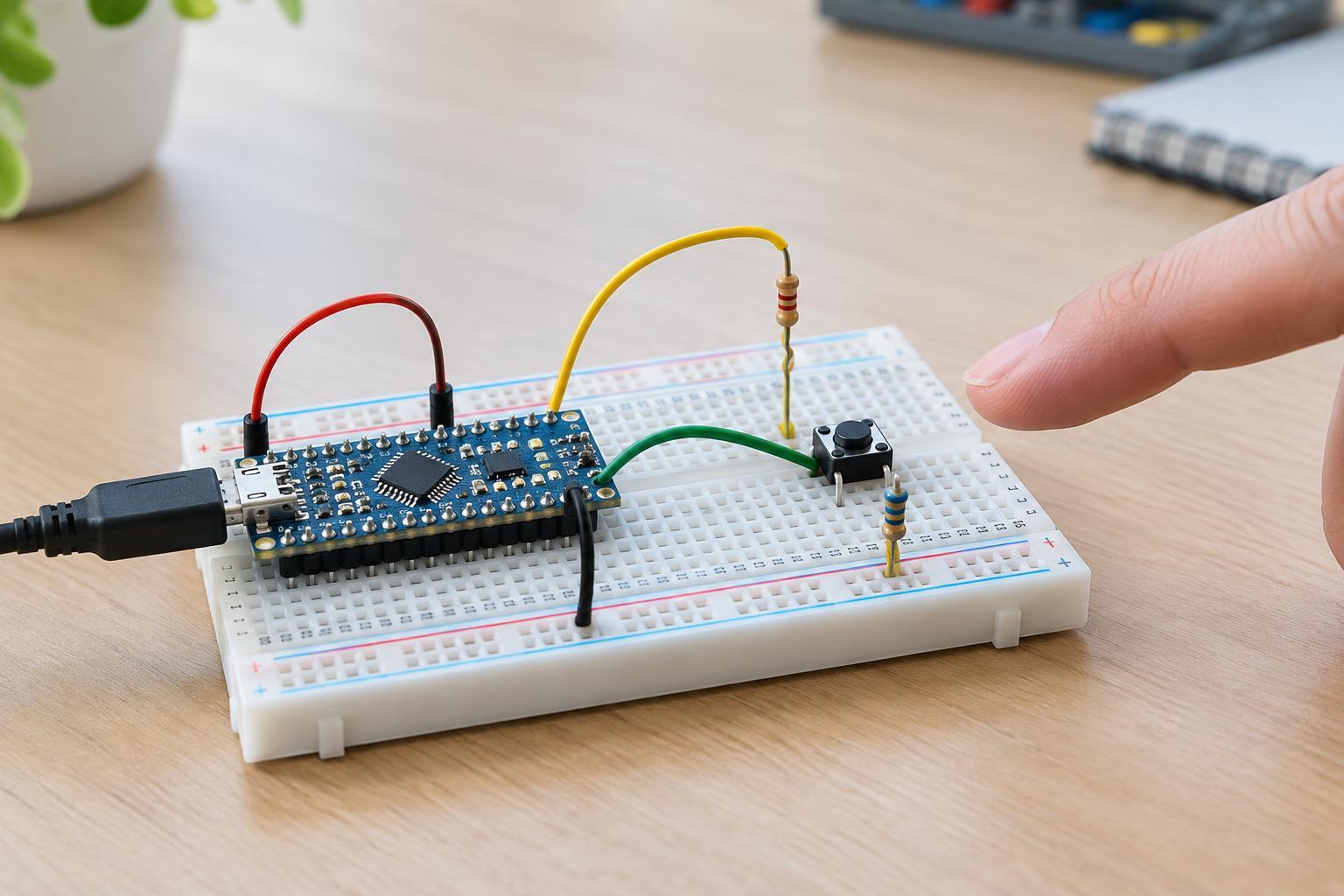
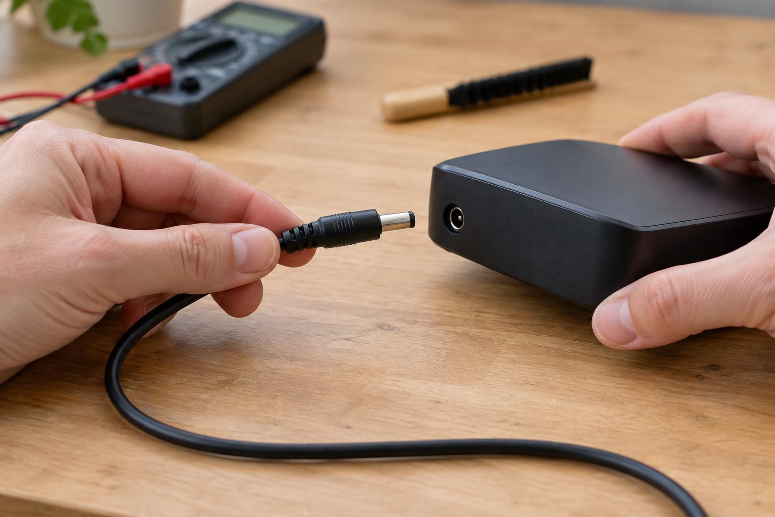
Keep this check to accessible, low-voltage circuits powered by suitable supplies. Disconnect power, including batteries and USB cables, and allow any stored charge to settle. Before using a meter, inspect the wiring: look for a ground lead in the wrong breadboard row, a split power rail that has not been linked, a loose terminal, or a connector installed backward. Follow the intended ground path from one module to the other.
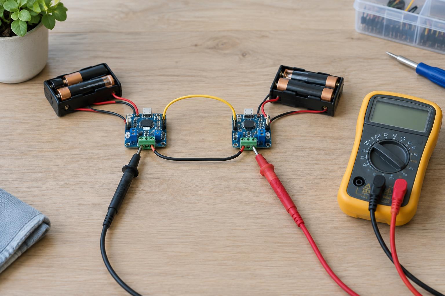
Set a multimeter to continuity or resistance mode and touch one probe to each module’s intended ground point. A low resistance or continuity indication supports that a conductive path exists; no indication may reveal a missing connection. Meter beeps alone do not prove a connection can carry operating current reliably, and readings through components can be misleading. If possible, test the actual wire or connector segment separately. Never use continuity or resistance mode on a powered circuit.
Measure the difference while operating
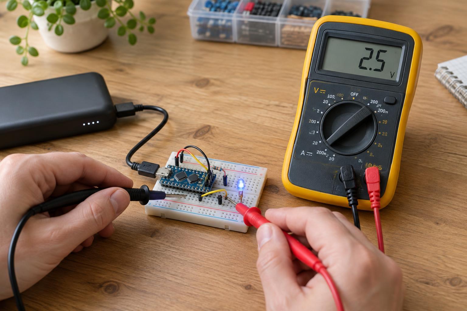
If the power-off check matches the intended wiring but communication still fails, a DC voltage measurement can provide another clue. Restore power, set the meter to DC volts, and measure between the two ground points while the modules operate. On an ordinary shared-ground connection, you would generally expect a small difference. A substantial or changing difference may point to a loose connection, an overloaded return path, or a mistaken assumption about how the supplies are connected.
Use insulated probe tips and avoid slipping across adjacent pins. Do not move a meter lead into its current-measurement socket for this test: a meter set up to measure current can create a short if placed across two points. A voltage reading by itself does not tell you whether it is safe to join two previously separate grounds. If the modules were not designed for a common reference, stop and check their connection requirements before changing the wiring.
Fix the cause, then test the signal
For modules that are supposed to share ground, repair the missing or poor connection rather than relying on a temporary probe or clip. Seat connectors fully, replace damaged leads, and make sure breadboard rails and terminal blocks carry the ground where you expect. If a ground wire also carries substantial load current, its voltage drop can disturb a sensitive signal reference; separating high-current return wiring from a signal return may help when the circuit design permits it.
After correcting the ground path, test the signal again. If the problem remains, check supply voltage at each module, signal-pin assignments, and logic-level compatibility. A shared ground is one requirement for many direct low-voltage connections, not a cure for every communication fault. Keeping the ground path visible in your wiring notes makes the next fault easier to find.