Start with a clearly bounded power path
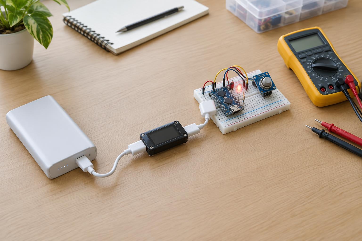
For a small maker project, treat the power bank as a finished 5 V USB supply. Use its normal USB output and a suitable cable or breakout designed for that connector. Do not open the power bank, attach wires to its internal battery, or attempt to charge bare lithium cells as part of this project. The useful question is whether the devices connected to the USB output can all run together within the bank’s output limits.
Read the rating for the specific port you intend to use. A bank with several ports may have a shared total output limit, so adding the individual port ratings may overstate what is available at once. If you use a USB-C connection, confirm that the arrangement supplies the voltage your project expects; do not assume a higher USB-C voltage is available or appropriate. Keep this project at the bank’s ordinary 5 V output unless you have equipment specifically designed for another negotiated voltage.
List every load and its operating states
Make a short inventory before connecting anything: controller board, sensors, displays, indicator LEDs, radio modules and any other powered device. Use the current figures for the actual parts and boards you have, rather than relying only on the current drawn by a chip in isolation. A development board may also power status LEDs, USB interface circuits or voltage regulators. Note whether each item runs continuously, switches on occasionally or has a higher startup demand.
Create two totals: an expected running current and a plausible simultaneous peak. For example, suppose a controller board uses 90 mA, a sensor uses 40 mA and a set of LEDs uses 120 mA. Their combined running load is 250 mA. If a radio can draw another 300 mA while transmitting, plan for at least 550 mA during that event, even if transmission is brief. These numbers are only an example; replace them with values for your build. If several loads can start or switch on together, budget for that overlap rather than assuming their peaks will never coincide.
Check the whole path, not just the bank’s label
Choose a power-bank output comfortably above the estimated peak, leaving room for uncertainty in component figures and future changes. The connected parts must also tolerate the voltage they actually receive. Many sensors and controller pins operate at 3.3 V even when the project takes power from a 5 V USB port. Use the board’s intended power input and any required voltage regulator or level shifting; never infer that a signal pin is 5 V tolerant just because the board has a USB socket.
Cables, connectors and converters are part of the budget. A thin or damaged cable can cause voltage drop when current rises, making a device reset even though the bank’s stated current limit seems sufficient. If a regulator converts 5 V to another voltage, its input current will not simply equal the current on its output. Check its input requirements, output rating and heat limits. Keep exposed conductors insulated and add loads only through connections rated for their expected current.
Separate peak current from runtime
The peak-current check answers whether the project is likely to keep running when demand rises. Runtime is a different estimate based on energy and average power. If a power bank gives a usable 5 V output-energy figure in watt-hours, divide that figure by the project’s approximate average power in watts for an initial runtime estimate. Average power at 5 V is approximately 5 multiplied by average current in amperes. Actual runtime may be shorter because of conversion losses, operating conditions and the bank’s cutoff behavior.
Be careful with a capacity figure stated only in milliamp-hours. It may describe the internal battery cells at their voltage, not the capacity delivered at the 5 V USB output. Do not divide that figure directly by your project’s 5 V current and treat the result as a reliable runtime. Also check whether the bank stays on at your lightest load: some banks shut off when a project draws very little current between active periods.
Measure, then revise the budget
Once assembled, test with a USB power meter or another appropriately rated measuring setup. Observe current during idle operation, normal use, startup and the most demanding activity you can safely trigger. A simple meter may miss very short peaks, so unexplained resets during switching or transmission still deserve investigation. Try a suitable shorter cable and review the load’s peak requirements before concluding that the bank is faulty.
Record the measured values alongside your original estimates. If the project approaches the output limit, reduce the load, spread out activities where the design permits, or select a suitable higher-rated supply. Avoid testing a suspected short circuit by repeatedly reconnecting the bank. A useful current budget is not a one-time calculation: it is a record you can update whenever you add a module, change a cable or alter how the project operates.