Why battery orientation matters
Many low-voltage projects have a positive supply connection and a negative return connection. Reversing them can put voltage across components in a direction they cannot tolerate. An LED, sensor board, microcontroller or polarized capacitor may fail quickly. A keyed connector and clear labels help prevent mistakes, but a protection component provides another layer of defense.
This guide is for small, low-voltage projects powered by a battery holder or a manufactured battery pack with appropriate built-in protection. Disconnect the battery before changing any wiring. Do not use these steps on mains-powered equipment, vehicle electrical systems, damaged batteries or loose rechargeable lithium cells. Reverse-polarity protection is not a substitute for a fuse, battery-management circuitry or safe charging practices.
Start with a series diode
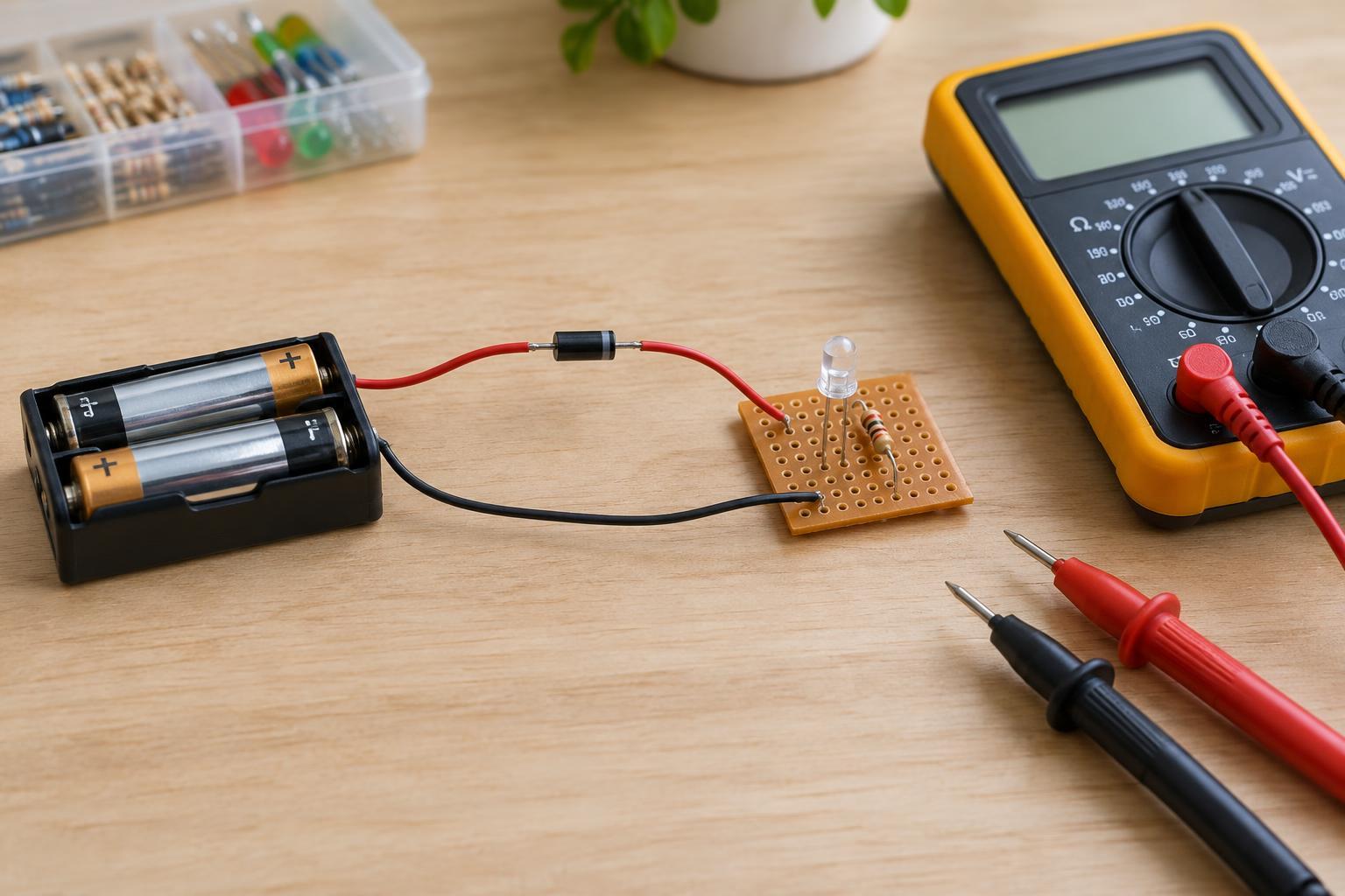
The simplest approach is to place a diode in the positive wire between the battery and the circuit. Connect its anode toward battery positive and its cathode toward the circuit’s positive input. On many through-hole diodes, a band marks the cathode; check the markings and datasheet for the part you actually have. Leave the negative return connected as the project requires.
With the battery installed correctly, current can pass through the diode. If the battery connections are reversed, the diode blocks current through that path. For this to protect the whole circuit, all power supplied from the battery must enter through the diode. A component connected directly across the battery on the unprotected side would not benefit from it.
Choose a diode with a suitable reverse-voltage rating and a forward-current rating above the project’s expected current, including any brief startup demand. A Schottky diode often has a lower forward-voltage drop than a comparable ordinary silicon diode, but the drop varies with current and temperature. That drop reduces the voltage reaching the circuit and produces heat in the diode. A device that barely runs at the battery’s lowest expected voltage may not tolerate the extra loss.
Decide whether a lower-loss option is needed
If diode voltage loss is a problem, a reverse-polarity protection module designed around a MOSFET may be an option. Once operating, an appropriately selected MOSFET can have a smaller voltage drop than a series diode. The trade-off is greater selection and wiring complexity: MOSFET pinouts, body-diode direction and allowable gate voltage all matter. A familiar-looking part wired like a diode will not necessarily provide the intended protection.
For a first project, a clearly documented module rated for the battery voltage and load current is more approachable than building an unfamiliar MOSFET circuit from loose parts. Follow the module’s input and output labels, and check whether it shares a negative return with the project. Whatever method you choose, place a fuse or other appropriate overcurrent protection close to the battery’s positive terminal when the battery can deliver enough current to overheat wiring in a short circuit. A reverse-polarity device does not limit current during a normal-polarity short.
Wire and check the project
Draw the power path before soldering: battery positive, any fuse, the protection device, then the circuit’s positive input. Mark the battery connector and circuit input so their polarity remains clear when the enclosure is closed. Keep connections insulated and secure; loose wires can bypass protection or cause shorts. If a battery holder has exposed contacts, remove the cells while working.
Before connecting power, use a multimeter to check which connector contact is positive and verify that the diode faces the intended direction. Look for accidental bridges between the positive and negative rails. Then install the battery in its correct orientation and measure the voltage at the circuit input. If the project does not start, disconnect power and check the diode direction and the voltage available after it rather than bypassing the diode immediately.
Do not deliberately reverse a battery to test the finished project. Someone experienced with a current-limited bench supply can test a protection circuit under controlled conditions, but a careful wiring inspection and a correct-polarity voltage check are the sensible starting points for most small projects. Protection is most useful alongside good connectors, clear labels and a habit of checking polarity before power-up.