Why current measurement needs a series connection
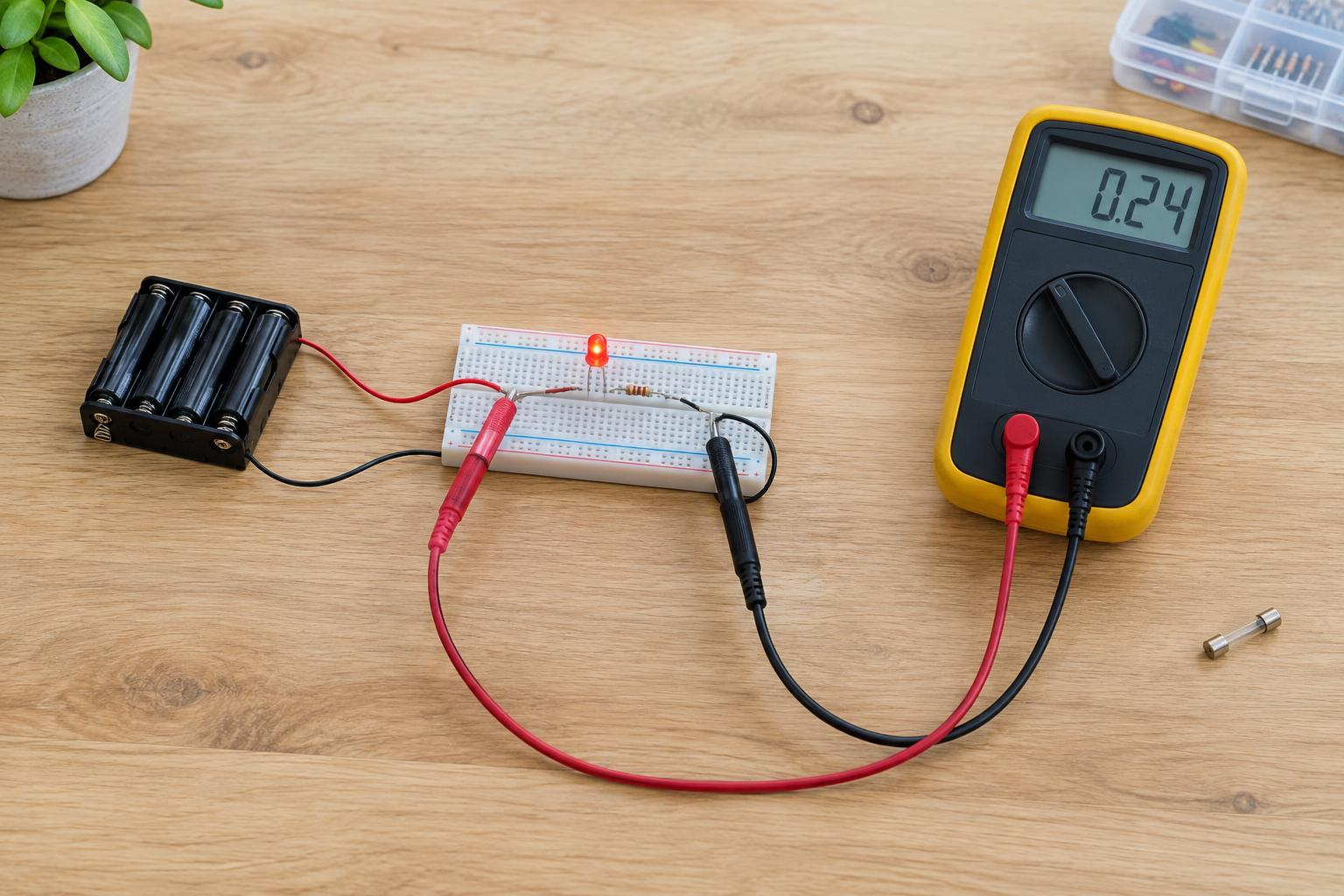
A voltmeter measures the difference between two points, so you place its probes across a component or supply. An ammeter measures the current flowing through a path, so the meter must become part of that path. In a simple battery-powered LED circuit, for example, you would open the circuit at one point and connect one probe to each side of that opening. Current then flows through the meter as well as the LED.
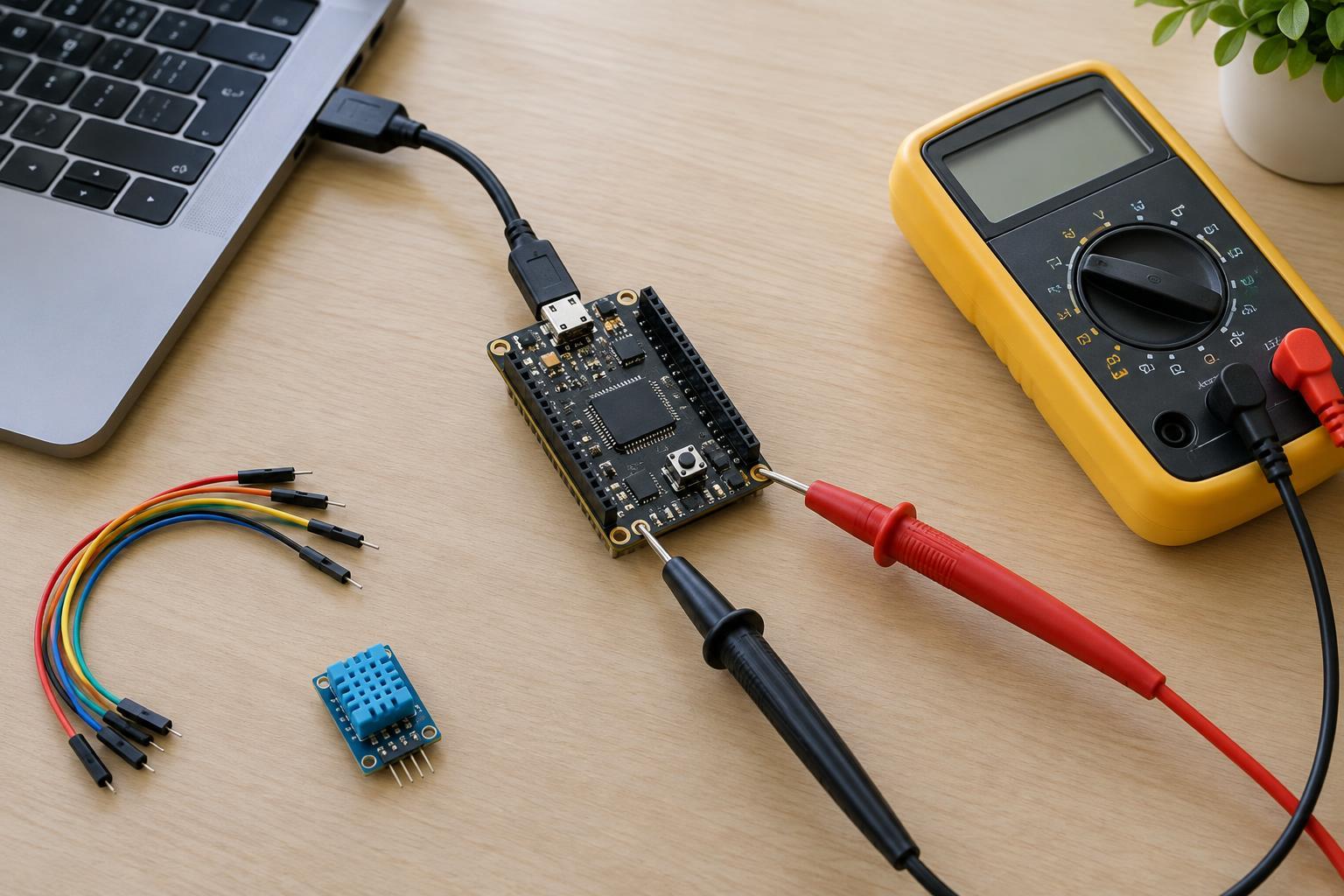
Never place a meter set to current measurement directly across a battery, power supply, or component as though you were measuring voltage. The current input presents a low-resistance path. Connected across a supply, it can act like a short circuit, potentially blowing the meter fuse, damaging equipment, or heating wires. Work only on low-voltage circuits whose supply and likely current you understand; this procedure is not for mains wiring or unknown power sources.
Plan the measurement before moving a probe
Start by switching off the project or disconnecting its supply. Identify the particular current you want to measure. To find the current through one branch, open that branch and insert the meter there. If the circuit has several parallel branches, placing the meter in the main supply path measures their combined current instead. A circuit sketch can help you choose the right opening before touching the wiring.
Estimate the expected current from the project’s design or component ratings. Then check the meter’s manual and markings for the permitted current, the appropriate input jack, and any time limit on higher-current measurements. Many meters have separate milliamp and amp inputs with different fuse protection and limits. If you cannot make a reasonable estimate, do not assume the meter can safely handle the current. Use a suitable current-limited bench supply or another measurement method if available.
Set up and connect the meter
With power off, put the black lead in the common jack and the red lead in the correct current jack. Set the meter to DC current for a DC-powered project. If the meter offers manual ranges and the expected current fits within its limits, begin on a range above the expected value; you can select a lower range later for better resolution. Check both the range and the input jack, because changing the dial alone may not make a low-current jack suitable for a larger load.
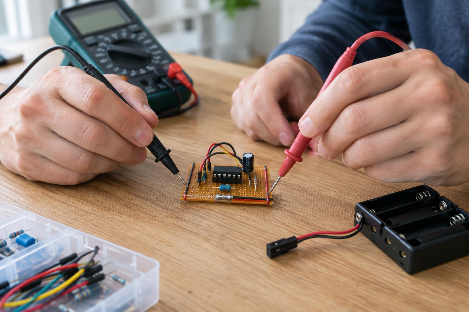
Open the intended connection and attach the probes across that gap so the meter completes the circuit. Secure the connections so loose probe tips cannot touch neighboring conductors. Restore power and read the display. A negative reading on a DC measurement usually means current is flowing opposite to the meter’s indicated direction; it does not, by itself, mean the circuit is faulty. Switch power off again before changing jacks, ranges that require rewiring, or probe positions.
When finished, disconnect power, remove the meter from the circuit, and restore the original connection. Move the red lead back to the voltage/resistance jack. That last step helps prevent an accidental short the next time you reach for the meter to measure voltage.
Understand fuse limits and unexpected readings
A meter fuse protects a specified current input under specified conditions; it does not make every connection safe. A brief startup surge or a stalled motor may draw more current than the device draws while running normally. Even when the steady reading seems modest, check whether the meter’s input and measurement-duration limits suit the circuit. High-current batteries, including some rechargeable packs, can deliver hazardous fault current despite their low voltage. Avoid inserting a handheld meter into a path that may exceed its ratings.
If the display shows an overload indication, switch off and reassess the input and range. If the circuit runs but the meter shows no current, a blown meter fuse is one possibility; an open connection or incorrect setup is another. Follow the meter’s instructions for checking its fuse. Replace a blown fuse only with the specified type and rating, including its voltage and interrupting ratings. Never bridge a fuse or substitute an arbitrary one.
When a direct measurement is not the best choice
Putting a meter in series slightly changes the circuit because the meter has some internal resistance. This can matter in sensitive or very low-voltage projects, where the resulting voltage drop may affect operation. An appropriately rated current-sense resistor, measured with the meter in voltage mode, can sometimes be a better design choice, but it also changes the circuit and must be selected for its power dissipation.
For larger currents, a clamp meter that explicitly supports DC current may let you measure around a single conductor without opening the circuit. Check its range and suitability for the expected current; clamping around both supply and return wires together will generally cancel the reading. Whatever method you choose, the key troubleshooting question comes first: which path’s current will this measurement actually show?