Set a safe boundary before testing
A short circuit is an unintended low-resistance path between points that should not be directly connected. On a 3–5 V prototype, a short between the positive supply rail and ground may overheat a wire, connector, battery, or component when power is applied. Finding that path while the circuit is unpowered is usually easier than diagnosing damage afterward.
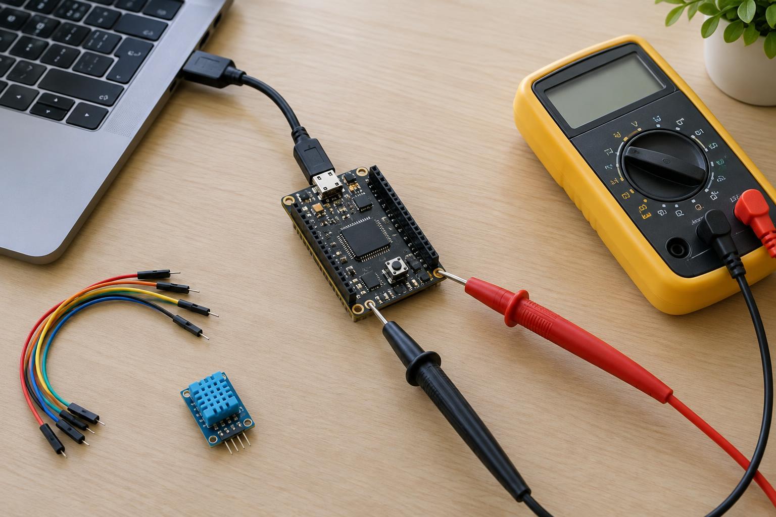
This procedure is for small, isolated, low-voltage circuits such as breadboard builds and simple prototype boards. Disconnect the power supply, USB cable, and batteries before touching the circuit with a meter. A USB connection counts as a power source even if the project appears switched off. Do not use this procedure to investigate mains wiring, exposed power supplies, or unfamiliar high-energy battery packs. If the circuit has large capacitors or has been connected to a higher voltage, stop until you know how to verify that it is safe to handle.
Inspect the build against its intended connections
Start with a wiring diagram or a simple list of which points belong to the positive rail and which belong to ground. Trace each power connection from its source through the prototype. On a breadboard, check where the terminal strips and supply rails actually connect; some rails are split, and rows that look adjacent may be electrically separate. On a soldered board, look for solder bridges, loose wire strands, component leads touching neighboring pads, and connectors installed in the wrong orientation.
Pay particular attention to the last change made. A newly inserted module, jumper, or connector is often quicker to examine than the entire build. Check component markings and pinouts rather than relying on package shape alone: similar-looking parts can put power and ground on different pins. Good lighting and a magnifier can reveal contact that is hard to see at arm’s length.
Check the supply rails with an unpowered multimeter
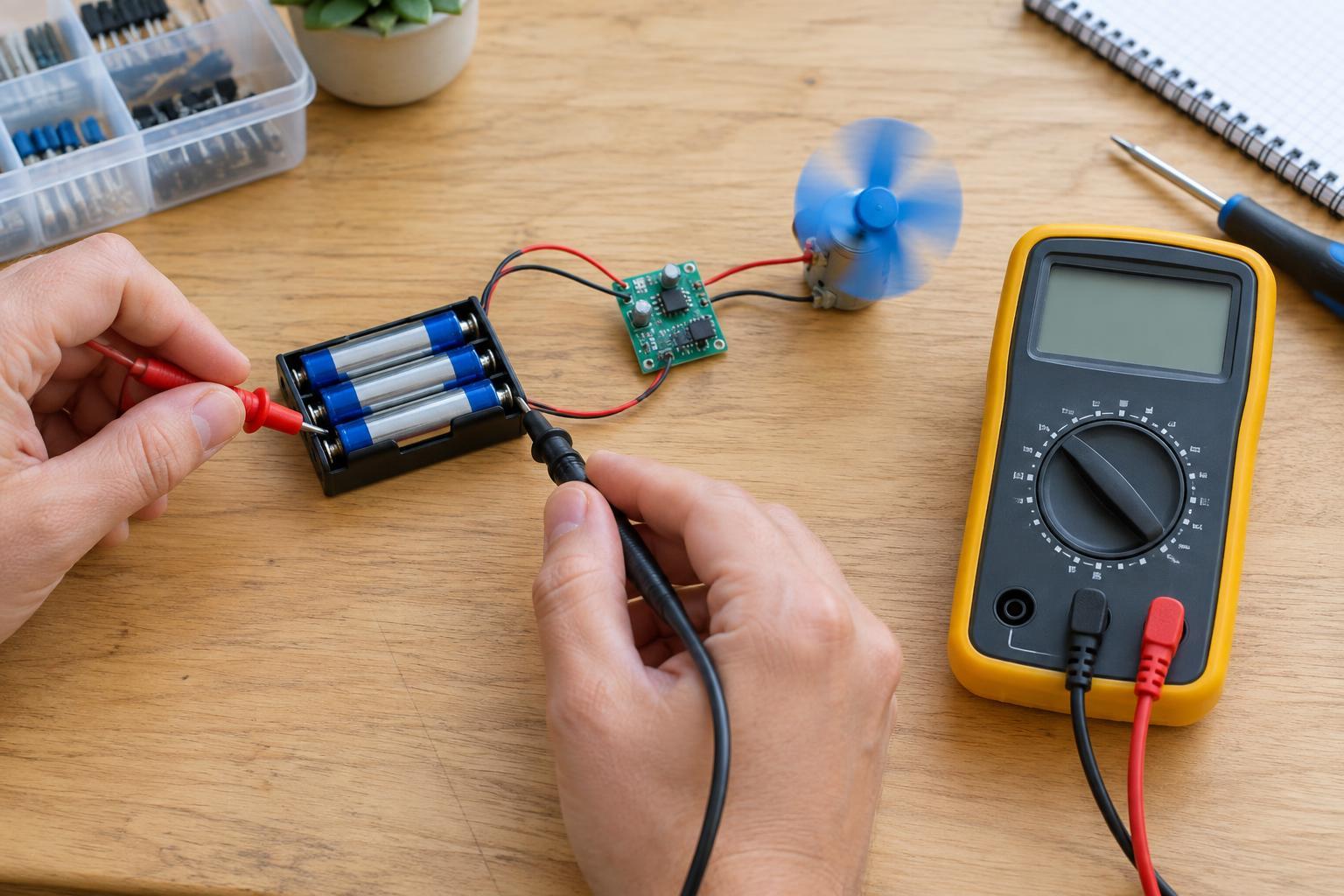
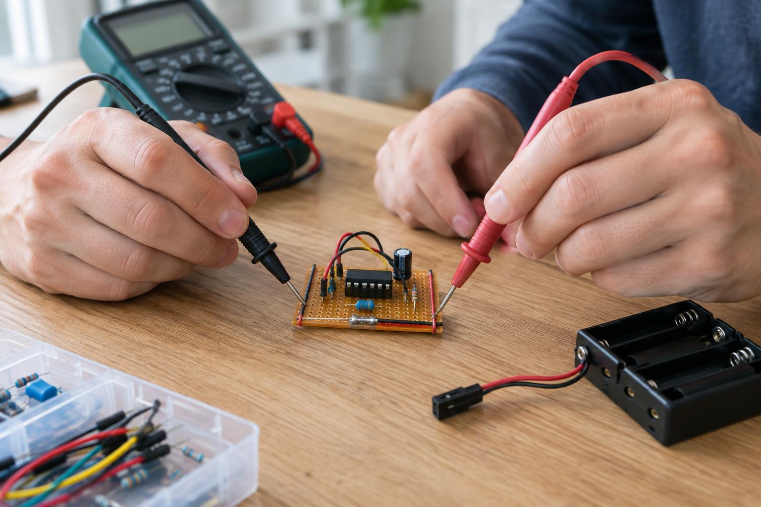
With every power source removed, set a multimeter to resistance or continuity mode and touch its probes together to learn how it indicates a near-zero-resistance connection. Then place one probe on the prototype’s intended positive supply input and the other on ground. Do not use resistance or continuity mode on an energized circuit; the meter supplies its own small test signal, and external power can make the reading misleading or damage the meter.
A steady reading close to the probe-together reading is a reason to investigate before powering up. It is not, by itself, proof of a fault. Some circuits have legitimate low-resistance paths, and a capacitor may briefly make the reading look low before it rises. Continuity beepers also vary in the resistance at which they sound. Record the resistance reading, wait for it to settle, and compare it with the circuit’s intended connections. If the result is unclear, consult the relevant component documentation rather than assuming a beep means a short.
Narrow down a suspicious path
If the supply rails appear nearly shorted, divide the circuit into sections while it remains unpowered. Remove plug-in modules and jumper wires one at a time, then repeat the same rail-to-ground measurement. If the low reading disappears after a section is disconnected, inspect that section and its connector closely. If it remains, continue tracing toward the power input. Make a note of what you removed so you can restore the intended wiring later.
For a breadboard build, separating the supply rail from one group of components at a time can identify the troublesome branch. For a soldered prototype, use existing connectors or removable links where possible; cutting traces or lifting integrated-circuit pins can create new faults and is best left out of a beginner-level check. A diode, indicator LED, or semiconductor input may also give different readings when the probes are reversed. Check both orientations and interpret the result in the context of the schematic.
Confirm the fix before connecting power
Once you find an apparent bridge or wiring error, correct it and repeat both the visual inspection and the unpowered rail measurement. Verify that the supply connector’s polarity matches the circuit, that no loose strands remain, and that removed modules are reconnected correctly. A normal-looking resistance reading cannot prove every part is wired properly; it only helps rule out certain faults.
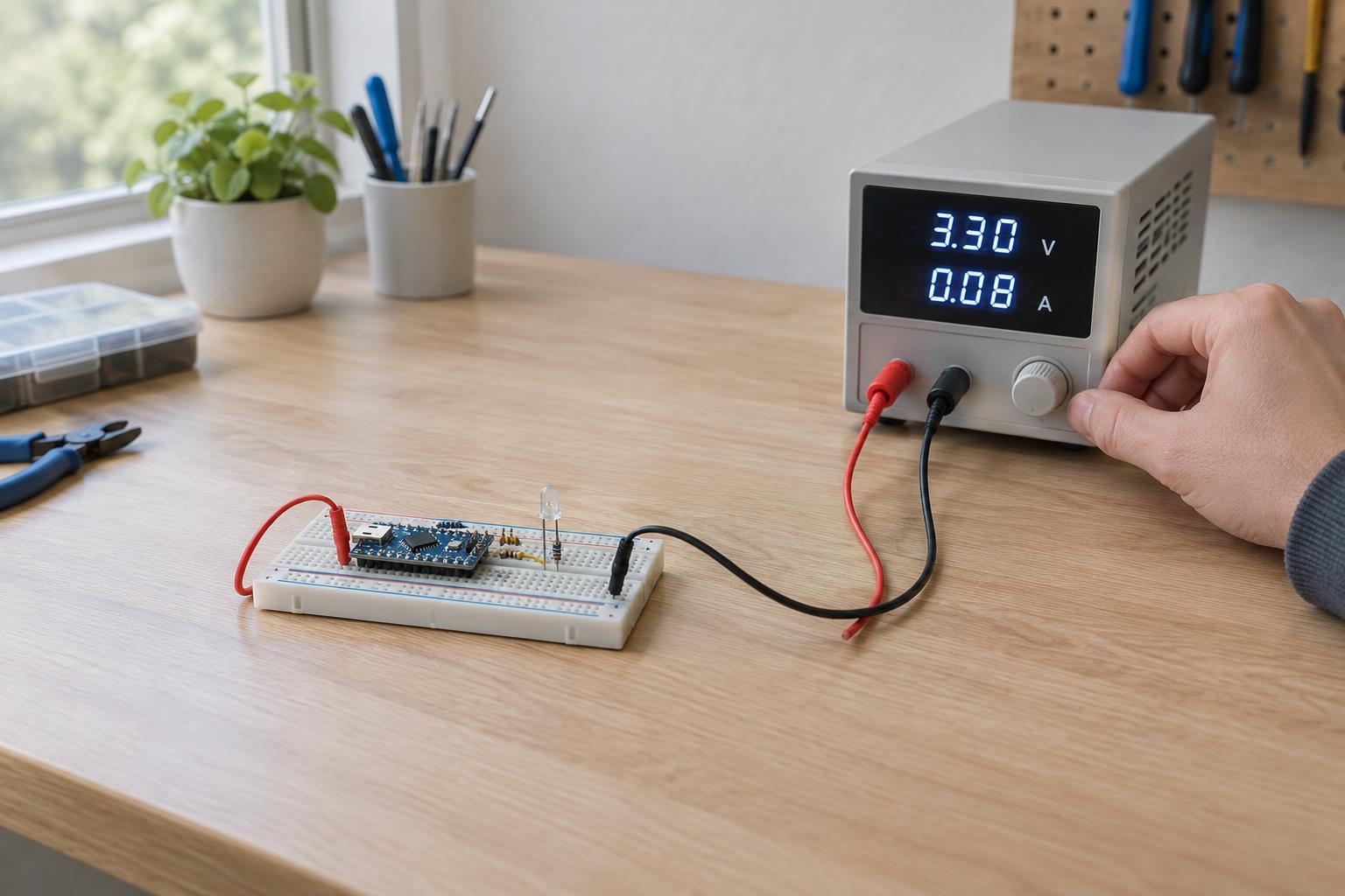
If the rails still measure almost like the probes touching together and you cannot explain why, leave the prototype unpowered. When the checks do make sense, use a supply set to the circuit’s intended voltage and, if available, an appropriate current limit for the components. Observe the first power-up closely and disconnect immediately if anything heats unexpectedly, smells unusual, or behaves differently from the plan.