What current limiting does—and does not do
A current-limited bench supply lets you set both an output voltage and a maximum output current. In normal operation, it holds the selected voltage. If the circuit tries to draw more than the current limit, the supply reduces its output voltage to keep current near that limit. Many supplies label these states constant voltage (CV) and constant current (CC). Check your supply’s display or manual so you know how it indicates each state.
This makes the supply useful for a first test of a small circuit designed for 3–5 V DC, but it cannot guarantee that parts will survive a wiring error. Even a limited current may damage a delicate component or heat a shorted connection. This procedure is for an unpowered, low-voltage board whose required voltage and polarity you know. It is not a method for testing mains-connected equipment, unknown power inputs, or a circuit with a battery still attached.
Inspect the circuit before connecting power
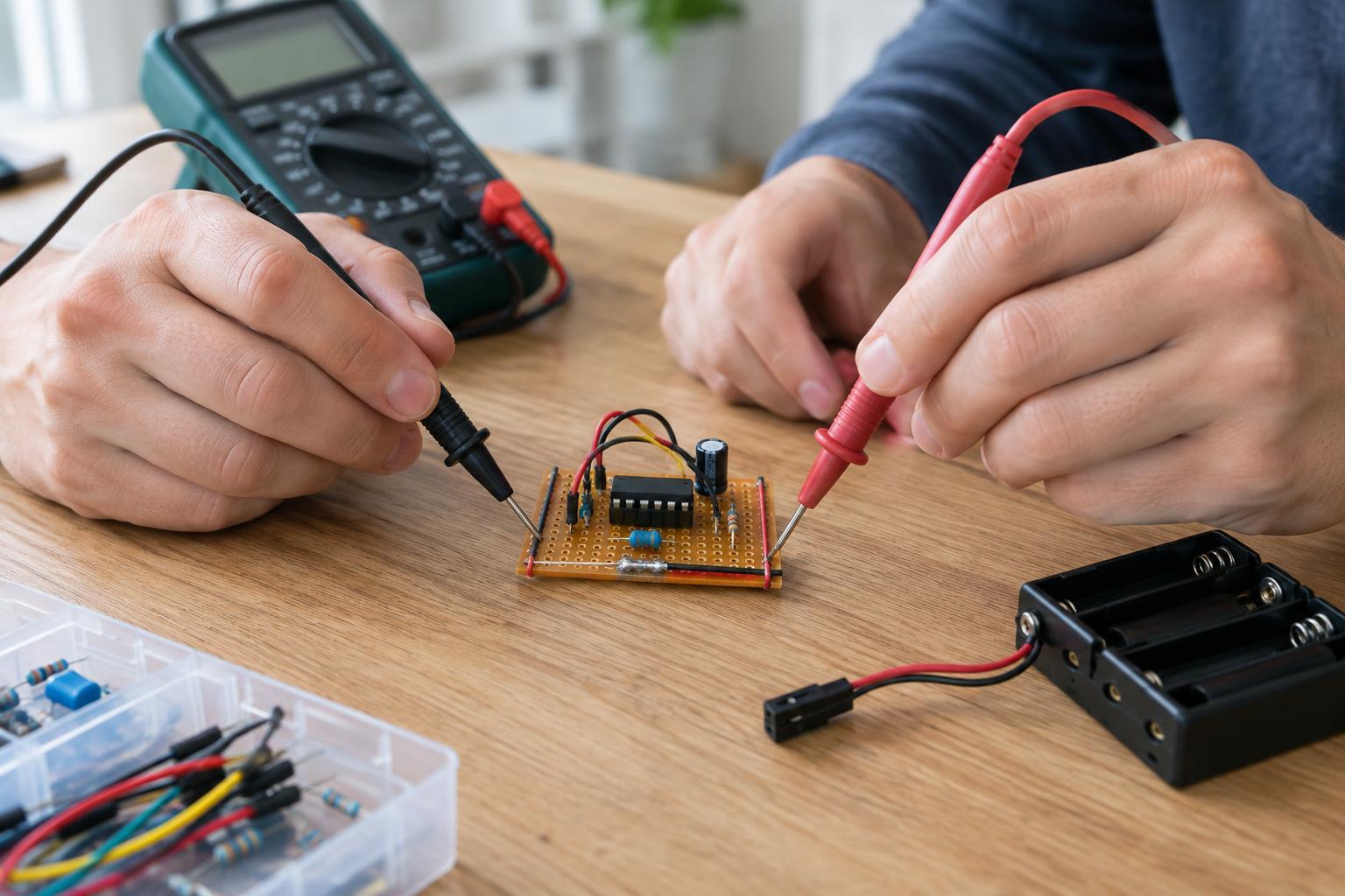
Find the circuit’s power and ground connections from its schematic, board markings, or component documentation. Check that every part on the power rail is rated for the voltage you intend to apply. Look closely for solder bridges, loose wire strands, reversed polarized capacitors, and connectors that could be plugged in backward. A continuity check between power and ground can reveal an obvious short, although a low resistance reading may also be normal for some circuits.
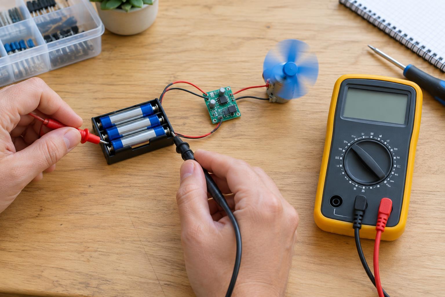
Disconnect batteries, USB cables, programmers, and other power sources unless the circuit is specifically designed to use them together. Disconnect optional loads, such as motors or LED strips, for the initial test if the core circuit can operate without them. Keep the board on a dry, nonconductive surface where you can reach the supply controls and see the circuit clearly. If the board has exposed conductors, arrange the leads so they cannot slip into contact with neighboring points.
Set voltage and current before enabling the output
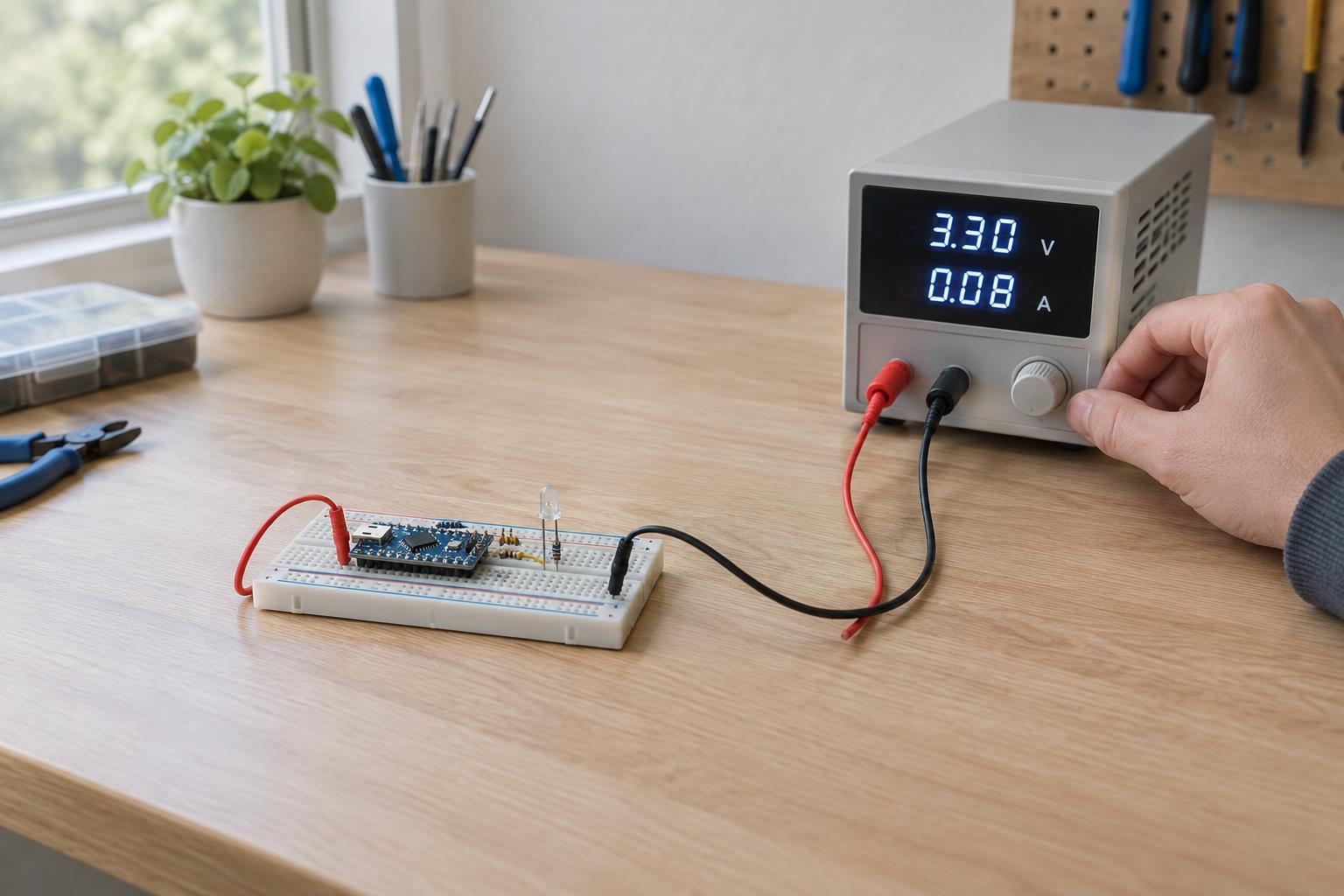
With the bench supply output off, set the voltage to the circuit’s specified value, such as 3.3 V for a 3.3 V design or 5 V for a 5 V design. Do not assume a device marked “3–5 V” will tolerate every voltage in that range at every input; confirm which connection you are powering. Check the supply’s output polarity and connect its positive lead to the circuit’s power input and its negative lead to ground.
Choose a current limit using the circuit’s expected normal draw, if you know it. Start low enough to reduce the energy available to a fault, but high enough for the circuit to begin operating; some boards briefly draw extra current as capacitors charge. If you do not know the expected draw, consult component information and test the smallest practical portion of the circuit first rather than selecting an arbitrary high limit. Set the limit according to your supply’s instructions; adjustment methods differ, and deliberately shorting output leads is not appropriate unless its manufacturer calls for that procedure.
Enable power and watch the first few seconds
Before switching on the output, make one final check of voltage setting, current limit, lead polarity, and exposed connections. Enable the output while watching the voltage and current displays. A brief current rise followed by a stable reading may simply reflect capacitors charging. If the supply settles in CV mode near the set voltage and the circuit behaves as expected, note the steady current. Add disconnected loads later, one at a time, checking the reading after each change.
If the supply remains in CC mode and its output voltage stays below the setting, the circuit is asking for more current than the chosen limit allows. That does not prove there is a short: the limit may be too low, or a legitimate load may have a higher startup demand. Do not repeatedly raise the limit just to make the voltage reach its target. Switch the output off first, then compare the reading with what the connected parts should reasonably draw.
Stop, isolate, and retest a fault
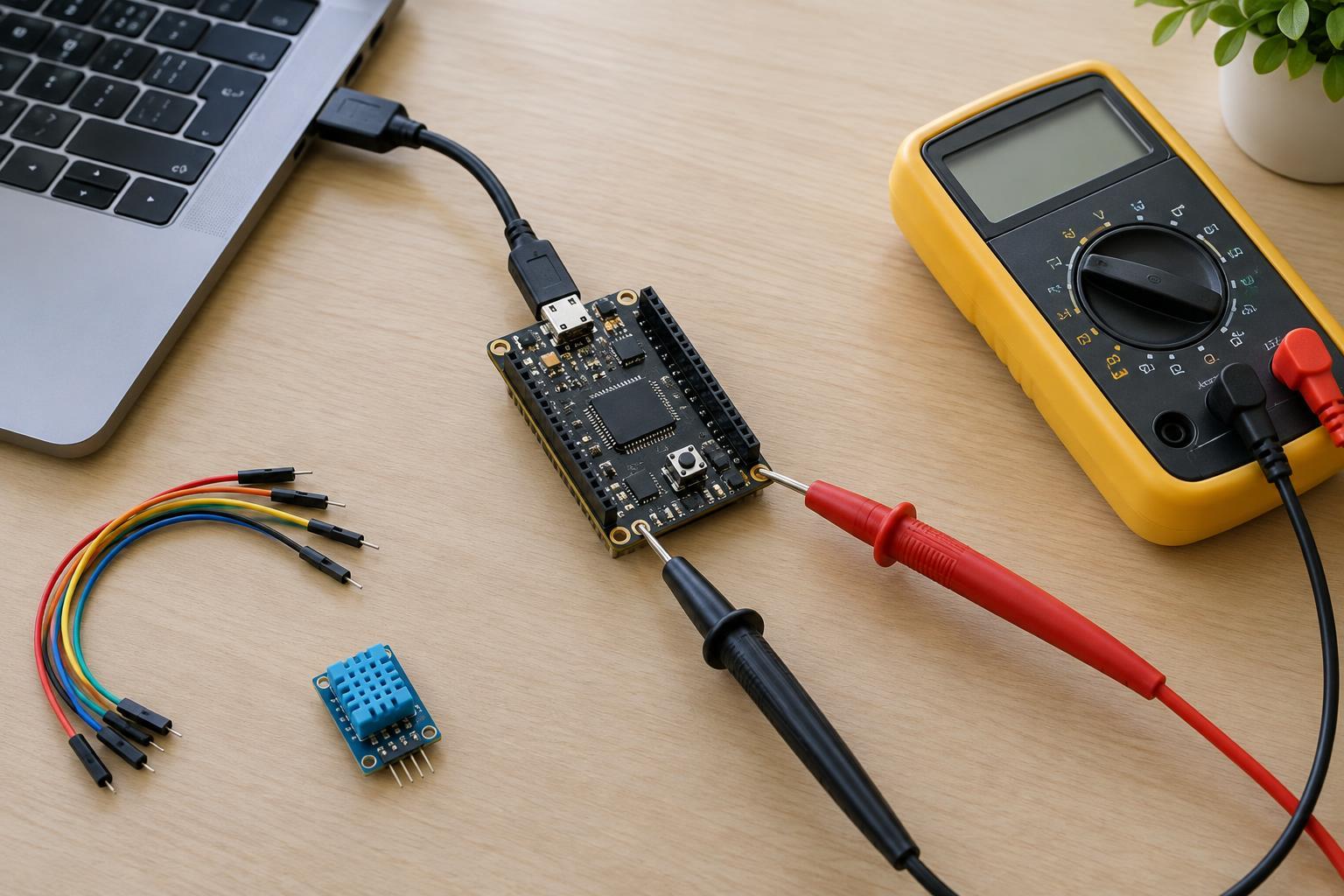
Turn the output off immediately if you notice smoke, an unusual smell, unexpected heating, or an unstable connection. Let hot parts cool before touching them. With power removed, recheck polarity and wiring, then inspect the power rail for solder bridges or misplaced components. If the circuit has separate sections, disconnect a section and retest at the original cautious settings to narrow down where excess current begins. A meter can help check continuity and voltage, but avoid moving probes across closely spaced live pins.
A successful first power-on establishes only that the circuit operated under those test conditions. It does not prove every input, output, or operating mode is safe. Record the voltage, steady current, and which parts were connected so later tests have a useful baseline. When finished, disable the supply output before removing the leads, and allow any capacitors time to discharge before handling or modifying the circuit.