What a PWM voltage reading represents
Pulse-width modulation, or PWM, switches an output between two voltage levels. Duty cycle is the fraction of each cycle spent at the high level: a signal that is high for one-quarter of each cycle has a 25% duty cycle. Changing that fraction can control the power delivered to a suitable load without requiring the output to sit at every intermediate voltage.
On its DC voltage setting, a multimeter may show an approximate average of those changing levels. For a signal that switches cleanly between 0 V and 5 V, the expected average is 5 V multiplied by the duty cycle. That gives about 1.25 V at 25% duty cycle and 3.75 V at 75%. The output is not necessarily producing a steady 1.25 V or 3.75 V; those numbers summarize its time spent high and low.
More generally, average voltage equals the low voltage plus the difference between the high and low voltages multiplied by duty cycle. This matters when the low level is not exactly 0 V or the high level is lower than the supply voltage. Estimating duty cycle from a meter reading is most useful when you know both levels and the reading is stable.
Set up a low-voltage check
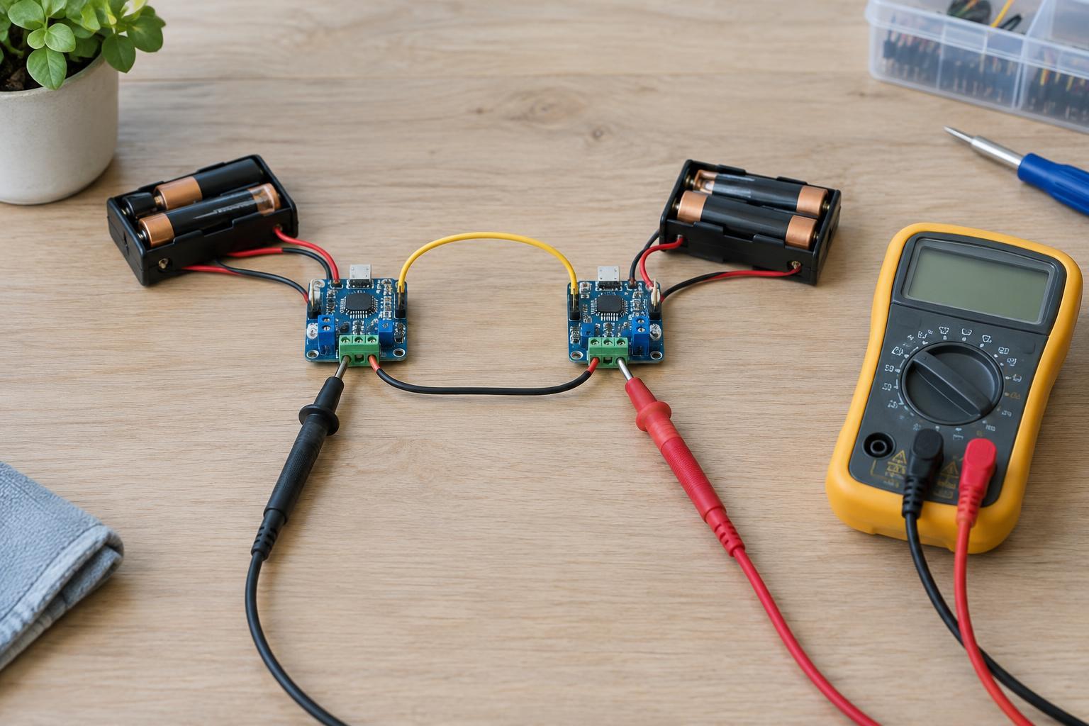
Keep this check to an accessible, low-voltage DC circuit that you are qualified to handle, such as a battery-powered maker board. Do not use these steps on mains wiring, an unknown power supply, a motor drive's power terminals or any circuit beyond your meter's and your own skill limits. Turn power off before attaching clips or changing connections, and keep probe tips from bridging adjacent pins.
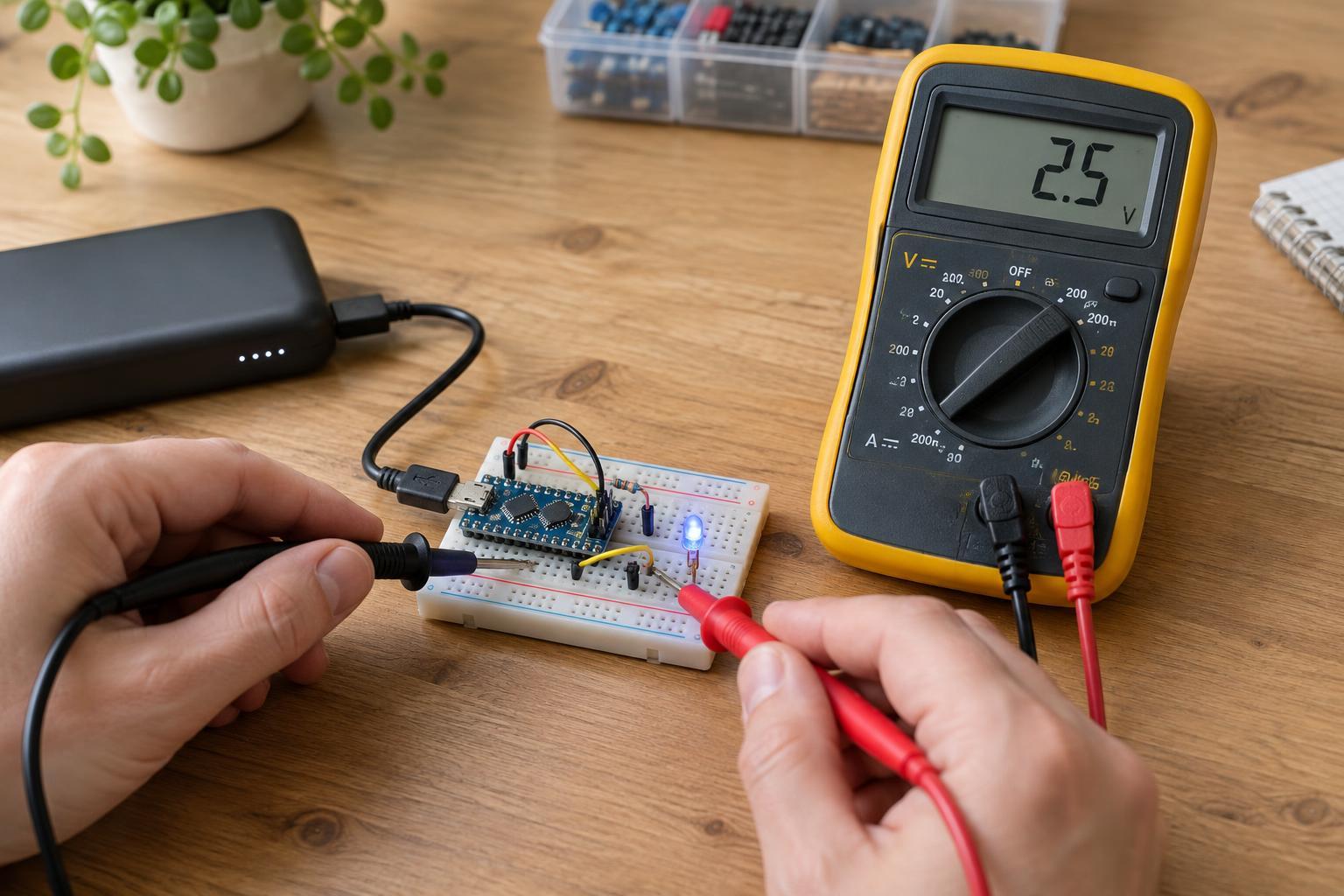
Put the black lead in the meter's common socket and the red lead in its voltage socket. Select DC volts and an appropriate range. Connect the black probe to the circuit's reference ground and the red probe to the PWM output, then power the circuit as intended. Check that you are measuring a voltage output, not inserting the meter in series as you would for a current measurement.
If possible, measure or confirm the output's low and high levels separately, perhaps by temporarily setting the controller to fully off and fully on. A 0% command may not pull every output to ground, and a 100% command may not reach the supply rail. An open-drain output, for example, depends on a pull-up resistor to establish its high level.
Turn the average into a useful estimate
Suppose a PWM pin measures 0 V when low and 3.3 V when high. At 25% duty cycle, its expected DC average is about 0.83 V; at 50%, about 1.65 V. If the meter displays roughly these values as you change the duty-cycle setting, that supports the conclusion that the output is switching and responding. Small differences do not automatically indicate a fault.
If the low and high levels are known, estimate duty cycle by subtracting the low level from the DC reading, then dividing by the difference between the high and low levels. For example, with a 0.4 V low level, a 3.0 V high level and a 1.7 V average, the estimate is (1.7 − 0.4) ÷ (3.0 − 0.4), or 50%. This calculation assumes the signal spends most of its time at those two levels rather than rising and falling slowly.
Measure under the operating conditions you care about. Connecting a load can change the high or low voltage, while disconnecting it can leave some outputs floating. A meter also has a high input resistance and may show a plausible voltage on a weak or unconnected signal. A voltage reading alone does not prove that an output can drive its intended load.
Know when the meter cannot tell the whole story
Meter response depends on the instrument and the PWM frequency. At a low frequency, the display may wander as the meter samples different parts of the cycle. At other frequencies, it may settle on an average; a stable display is still not proof that every pulse has the right width or shape. Consult your meter's specifications if you need to know its frequency and duty-cycle measurement limits.
Do not treat a reading on the AC voltage setting as the missing high-level voltage. AC modes vary in how they handle a DC offset and in what waveform or frequency range they measure accurately. Likewise, a DC average is not the same as the RMS voltage used in some power calculations. A meter with a duty-cycle function may report the timing directly, but only if the signal meets that function's input requirements.
If you need to verify pulse frequency, brief glitches, rise time or exact duty cycle, use an appropriately rated oscilloscope or logic analyzer with a safe connection to the circuit reference. For a basic low-voltage check, start with the DC reading, compare it with the expected average, and treat any mismatch as a reason to check the signal levels, ground connection, load and meter limitations before drawing a conclusion.