Two ways to turn a magnetic field into a signal
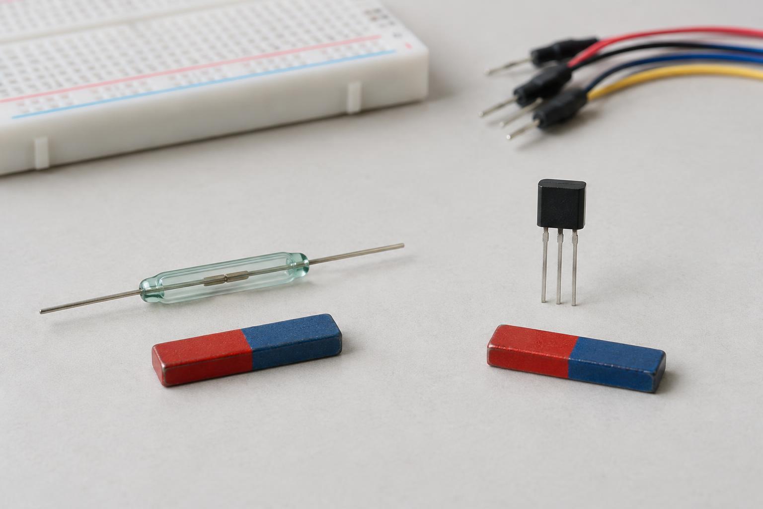
A reed switch contains thin metal contacts sealed inside a small glass capsule. In a common normally open version, a nearby magnet pulls the contacts together and closes the circuit. Remove the magnet, and the contacts separate. Other contact arrangements exist, so check the part rather than assuming it is normally open. Because it is a mechanical contact, a reed switch can be tested much like an ordinary switch.
A Hall-effect sensor uses an electronic sensing element to respond to a magnetic field. For a simple magnet-detection project, you will usually want a digital Hall sensor that changes its output state when the field crosses a threshold. Hall devices also come in analog versions whose output varies with field strength. That distinction matters: an analog part is not a direct substitute for an on-off switch.
Neither device measures distance by itself. A magnet may trigger one at a particular position, but that position depends on the magnet’s strength and orientation, the sensor’s placement, and nearby materials. Treat the detectable gap as something to verify in the finished assembly.
The differences that affect a project
A reed switch needs no power to operate its contacts. That makes it convenient for a simple battery-powered input that is checked only occasionally. Its contacts can carry a small circuit signal directly, provided the voltage and current stay within the switch’s ratings. The glass body is fragile, however, and the contacts can briefly bounce between open and closed as they move. Software debouncing, or an appropriate circuit, can prevent one movement from being counted several times.
A Hall-effect sensor generally needs a suitable supply voltage and draws some current even while waiting for a magnet. It has no moving contacts, so contact bounce and contact wear are not concerns. Its output still needs attention: some digital Hall sensors actively drive a high or low level, while others have an open-collector or open-drain output that requires a pull-up resistor. Check the part’s pinout, supply range and output type before connecting it to a controller.
Magnet polarity can also change the result. Some Hall sensors respond to one magnetic pole, some respond to either pole, and latching types change state with one pole and reset with the opposite pole. Reed switches generally respond to a suitable field without requiring a particular pole, although orientation can strongly affect their operating gap. These differences make the exact sensor model and magnet position more useful design information than the words “Hall” or “reed” alone.
Choosing for a door, wheel or position detector
For a cabinet-door indicator, a reed switch is often the simpler starting point: mount the switch on the fixed frame and the magnet on the door, then arrange them so the contacts change state reliably as the door opens and closes. If a project must distinguish between the presence of a north-facing and south-facing magnet, an appropriately specified Hall sensor offers options a basic reed switch does not.
For a rotating wheel or moving mechanism, either device can produce a pulse when a magnet passes. A Hall sensor may be attractive when movement is frequent because it has no moving contacts. A reed switch may be adequate at a modest rate if its mechanical limits and any contact bounce are accounted for. In either case, keep the magnet secure and test the signal at the fastest movement the project is expected to see.
Consider how you want the circuit to behave when a wire is disconnected. A normally closed reed contact, for example, can give a different disconnected-wire indication than a normally open contact. Hall outputs have their own default states and may behave differently when unpowered. Choose the input arrangement based on the states your controller can actually distinguish, rather than assuming that “no magnet” and “broken connection” will be distinguishable.
Wiring and testing safely
Keep a first experiment within a low-voltage circuit powered by a current-limited bench supply or an appropriate small battery. Do not use either sensor as an excuse to work directly on mains wiring. Put a reed switch in series with a current-limited indicator or connect it to a controller input using that controller’s recommended input resistor arrangement. Do not connect it across a battery without a load: a closed switch would create a short circuit.
For a Hall sensor, identify every pin from the specific part’s documentation before applying power; similar-looking packages can have different pin orders. Confirm that the sensor’s supply and output levels suit the controller. If its output is open-drain or open-collector, add a pull-up to a compatible voltage unless the input already provides one. An LED also needs a current-limiting resistor, whether it is driven by a sensor output or a controller.
Start with the magnet farther away, then approach the sensor slowly from several directions while observing the output. Turn the magnet around and repeat. Mark the positions that give dependable changes, allowing some margin so small mounting shifts do not cause intermittent detection. Avoid bending leads close to a reed switch’s glass seal, and keep loose magnets away from items that could be damaged or unexpectedly attracted.
When the signal does not behave as expected
If a reed switch never changes state, check it with a low-voltage continuity test, then try rotating or moving the magnet before replacing the part. If it changes state but produces extra counts, look for contact bounce in the input reading and add debouncing. If it works by hand but not when mounted, inspect the gap and alignment.
For a Hall sensor, first verify power, ground, pin order and the presence of a pull-up if its output needs one. Next, check whether the sensor requires a particular magnetic pole or latches until the opposite pole arrives. An apparently stuck output may be normal behavior for a latching model. Testing these details separately is usually more useful than moving the magnet at random.