Two sensors, two different measurements
An accelerometer measures specific force along its sensing axes. In everyday projects, its output reflects both motion and the effect of gravity. Leave a three-axis accelerometer still on a table and its readings will generally show about one g along the direction of gravity, distributed among the axes according to how the board is tilted. That makes it useful for detecting a change in orientation, as well as a bump or shake.
A gyroscope measures angular rate: how quickly the sensor is rotating around each axis. It does not directly report an absolute angle. To estimate how far a board has turned, software adds up its rate readings over time. A gyro is therefore good at following quick turns, even when the device is moving in ways that confuse an accelerometer. Many small inertial measurement units, or IMUs, package both sensors together because their strengths complement each other.
Why accelerometer-based angles can be misleading
When a device is still, gravity provides a useful reference for estimating pitch and roll: roughly, its forward-back and side-to-side tilt. But an accelerometer cannot label part of its reading “gravity” and another part “movement.” If you push a board sideways, it may briefly appear tilted to an algorithm that assumes every measured force comes from gravity. Vibration and impacts can produce similar errors.
This is why an accelerometer can give a steady long-term tilt reference without giving a clean angle at every instant. Smoothing its readings may make an estimate less jumpy, but too much smoothing also makes it slow to respond. An accelerometer alone cannot establish heading, or yaw, from gravity: turning a level board like a compass needle does not change which way gravity points.
Why a gyro angle drifts
A gyro reading can be slightly nonzero even when the device is perfectly still. That offset is called bias. Temperature changes, noise and the sensor’s own limitations can also affect the reported rate. When software integrates rate into angle, it adds those small errors along with the real rotations. Over time, the estimated angle can wander away from the actual orientation. This is gyro angle drift; it does not necessarily mean the physical sensor is rotating.
Timing matters too. The calculation needs to know how much time passed between readings. If software assumes a fixed interval while the actual interval varies, its angle estimate can become less reliable. Drift is particularly noticeable for yaw when using only an accelerometer and gyro: gravity can help correct pitch and roll, but it offers no heading reference to correct yaw.
Using the sensors together
A common approach uses gyro readings to track short-term changes and accelerometer readings to gently correct pitch and roll over time. This is often called sensor fusion. A complementary filter is one relatively simple way to do it: it gives the gyro more influence over quick motion and the accelerometer more influence over slow correction. More elaborate filters use the same basic idea while accounting for additional conditions.
No filter can turn ambiguous measurements into certainty. During prolonged acceleration, the accelerometer may be a poor gravity reference. Without another suitable reference, yaw may continue to drift. A magnetometer can sometimes provide heading information, but nearby magnets, motors or metal objects can disturb it. Choose the sensors and accuracy expectations to match what the project actually needs; a gesture detector and a navigation system place very different demands on orientation estimates.
A safe first test and troubleshooting checklist
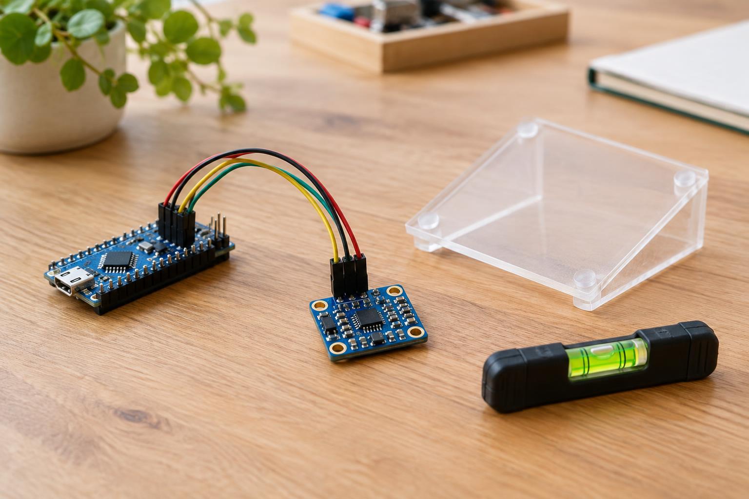
For a first experiment, use an IMU breakout board with a compatible low-voltage microcontroller. Check the board’s documented supply voltage and logic levels before wiring it, and disconnect power while changing connections. Keep the project on its intended low-voltage supply; there is no need to work with household mains power to explore these sensors.
Log the raw readings while the board rests, then rotate it slowly around one axis at a time. Note which accelerometer axis changes with tilt and which gyro axis responds during each turn. If a gyro axis reports a persistent rate while still, measure its resting offset and subtract it in software. Also check that your code uses the correct units and the actual time between samples. If a tilt estimate jumps during a shake but settles afterward, that may be the expected effect of motion on the accelerometer rather than a wiring fault. If it steadily wanders while untouched, examine gyro bias, timing and whether your algorithm has a long-term reference.