What a fixed resistor does
A fixed resistor has a nominal resistance, measured in ohms (Ω). In a circuit, it can limit current, divide voltage with other resistors, or help set an operating point. Unlike an adjustable resistor, its intended value does not change when you turn a knob. Its actual resistance may still vary slightly from its marked value and may change with temperature.
A resistor is chosen for more than its ohm value. Its tolerance describes how far its resistance may be from the nominal value. Its power rating describes how much heat it is designed to dissipate under specified conditions. Physical size and construction also matter: a tiny surface-mount part and a larger leaded part with the same resistance may have different ratings.
Reading color bands on leaded resistors
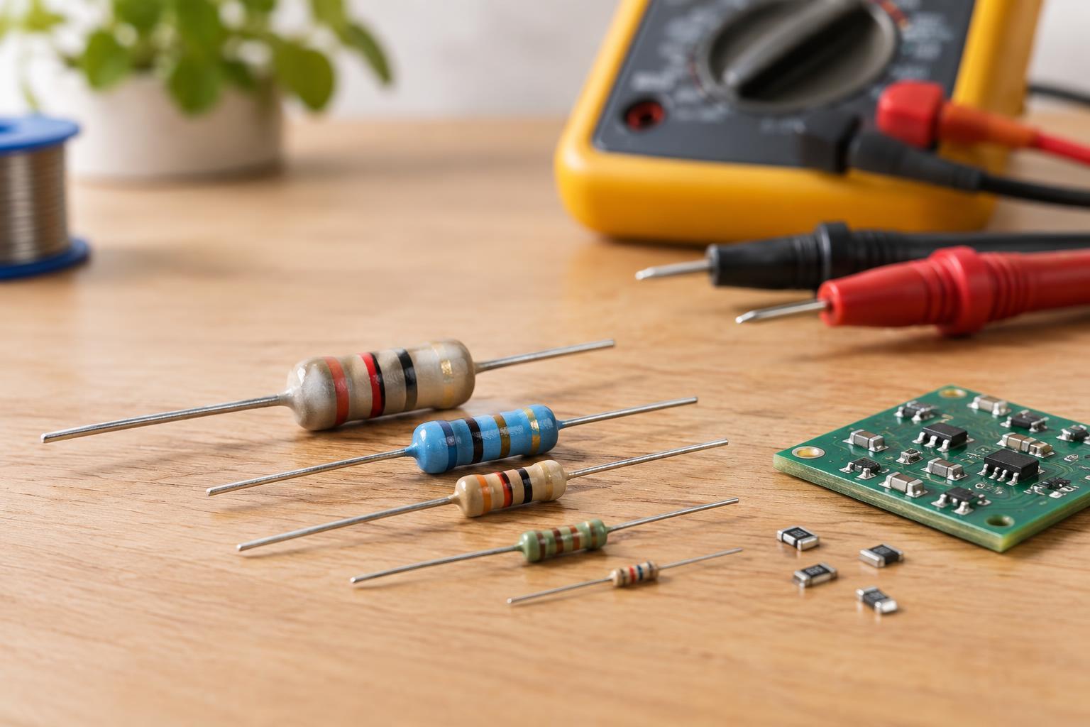
On a common four-band resistor, the first two bands give digits, the third is a multiplier, and the fourth gives tolerance. The digit colors are black 0, brown 1, red 2, orange 3, yellow 4, green 5, blue 6, violet 7, gray 8, and white 9. A brown-black-red-gold resistor is 10 × 100, or 1,000 Ω (1 kΩ), with ±5% tolerance. Gold can also be a ×0.1 multiplier and silver a ×0.01 multiplier when either appears in the multiplier position.
A common five-band scheme uses three digits, followed by a multiplier and a tolerance band. Brown-black-black-red-brown, for example, reads 100 × 100, or 10 kΩ, with ±1% tolerance. A sixth band, when present, may specify temperature coefficient. Band conventions can differ on unusual or specialized parts, so check the part documentation if the pattern does not make sense.
To find the reading direction, look for a tolerance band set apart from the others; gold or silver at one end often makes orientation easier. If the colors are faded or ambiguous, do not force a guess. You can measure a loose resistor with a multimeter set to resistance. Turn power off first, and remember that a measurement taken while the resistor remains connected in a circuit may be affected by other components.
Interpreting printed values and tolerance
Many surface-mount resistors use printed codes instead of bands. In a common three-digit code, the first two digits are significant and the last gives the number of zeros: 472 means 47 followed by two zeros, or 4.7 kΩ. A common four-digit code uses three significant digits: 1001 means 100 followed by one zero, or 1 kΩ. Other marking systems exist, and very small parts may have no visible marking, so a printed code is not always enough to identify a component.
Tolerance is a range around the nominal value, not a promise that every part will sit at one edge of that range. A 1 kΩ resistor with ±5% tolerance may measure from 950 Ω to 1,050 Ω under the conditions used to specify it. Common tolerance bands include gold for ±5%, silver for ±10%, brown for ±1%, and red for ±2%. A tighter tolerance can be useful in a precise voltage divider, but it does not replace checking how the rest of the circuit affects the result.
Checking the power rating
Current through a resistor produces heat. For a steady condition, calculate its power dissipation as P = I²R, where I is the current through it, or P = V²/R, where V is the voltage across that resistor. If 5 V is across a 1 kΩ resistor, the calculation gives 0.025 W, or 25 mW. Use the voltage across the resistor—not automatically the circuit’s supply voltage—when applying the second formula.
Choose a rating above the calculated dissipation rather than right at it. How much margin is appropriate depends on enclosure temperature, airflow, nearby heat sources, and whether the circuit has startup or pulse loads. A power rating also does not override a resistor’s separate voltage or pulse limits. If a part becomes unusually hot, stop and check the circuit rather than simply installing a higher-rated replacement.
A practical selection and measurement routine
For a low-voltage project, start with the required resistance, then decide how much tolerance the circuit can accept. Calculate the highest expected steady-state dissipation and select a suitable power rating and physical package. If pulses, high voltages, or substantial heating are involved, consult the component’s specifications instead of relying on a color code or body size alone.
Before measuring resistance, disconnect the power source and avoid shorting batteries with meter probes or loose leads. Measure a loose part when possible; if it is installed, other circuit paths can make an in-circuit reading misleading. Keep beginner work to low-voltage circuits. Mains-connected equipment and circuits with capacitors that may retain hazardous charge require different precautions and are not suitable places to practice resistor identification.