What an LED needs to light
A light-emitting diode, or LED, conducts primarily in one direction and emits light when current flows through it. Unlike a small incandescent bulb, a typical indicator LED should not be connected directly across a voltage source. Once it begins conducting, a modest increase in applied voltage can cause a large increase in current. Too much current can damage the LED, even if it lights briefly at first.
Three specifications help you plan a simple circuit: forward voltage, forward current, and polarity. Forward voltage describes the voltage across the LED while it is operating at a stated current. Forward current is the current flowing through it in the conducting direction. Polarity tells you which way to connect it. These specifications work together; none is a substitute for a current-limiting component.
Reading forward voltage correctly
An LED’s forward voltage, often written as Vf, is not a fixed voltage that it draws from any supply. It depends on the particular LED, its operating current, and temperature. Its datasheet may give a typical value and a range measured at a specified current. Different LED colors and constructions can also have different forward-voltage ranges, so the value for one LED should not automatically be used for another.
For a resistor-limited circuit, forward voltage helps you estimate how much of the supply voltage must be dropped across the resistor. If the supply voltage is too close to the LED’s forward voltage, small variations in the supply or LED may make brightness inconsistent. If the supply is lower than the voltage needed for useful conduction, the LED may be dim or remain off. Check the LED’s datasheet when its identity is known; otherwise, treat an assumed Vf as an estimate and start conservatively.
Current ratings are limits, not targets
A datasheet may list a recommended operating current as well as an absolute maximum forward current. The absolute maximum is a boundary to avoid, not a suggested brightness setting. An indicator LED may be visible at a current well below its maximum, depending on the device and surroundings. Starting with a modest current reduces heating and makes it easier to adjust brightness without stressing the component.
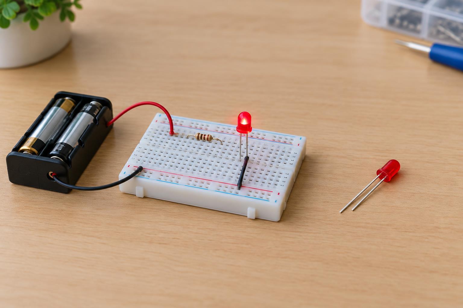
A resistor in series is a straightforward current limiter for a single LED on a reasonably stable low-voltage supply. Estimate its resistance using R = (supply voltage − LED forward voltage) ÷ desired current, with current expressed in amperes. For example, with a 5 V supply, an estimated 2 V LED forward voltage, and a desired current of 0.01 A, the calculation gives 300 ohms. A 330-ohm resistor would give an estimated current of about 9 mA. Check that the resistor’s power rating comfortably exceeds the power it will dissipate; in this example, the estimate is about 0.03 W.
Finding and checking polarity
The anode is the LED terminal that connects toward the positive side of the supply; the cathode connects toward the negative side. On many through-hole LEDs, the longer lead is the anode and a flat edge on the body marks the cathode. These clues are useful but not infallible: leads may have been trimmed, and package markings vary. Surface-mount LEDs often use a printed mark whose meaning must be checked against the part’s documentation.
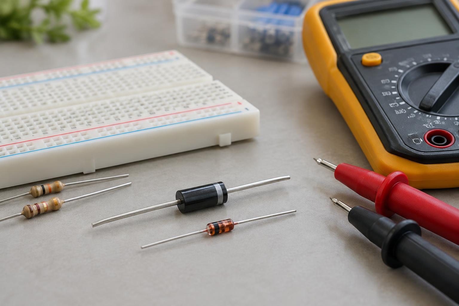
If you are unsure, a multimeter’s diode-test setting may help identify the conducting direction. Some LEDs glow faintly during this test, while others may not visibly light even when connected correctly. A reverse-connected LED generally will not light in a simple low-voltage circuit, but do not assume LEDs can withstand arbitrary reverse voltage. Follow the device’s rating, and disconnect power before changing connections.
Putting the specifications together
For a first test, use a low-voltage source within the ratings of every part, one LED, and one series resistor. Connect the resistor and LED in series, observing the LED’s polarity. The resistor can go on either side of the LED because the same current flows through both series components. Before applying power, verify the supply voltage, resistor value, and connections. If the LED does not light, switch off the supply before checking polarity and continuity.
For multiple LEDs, do not assume that placing them in parallel behind one shared resistor will divide current equally. Small differences in forward voltage can make one branch carry more current than another. Give each parallel LED branch its own current-limiting resistor, or use a suitable LED driver where precise control is needed. When planning series LEDs, add their estimated forward voltages and leave enough supply voltage for the current limiter. These habits make low-voltage LED experiments easier to troubleshoot and less likely to damage components.