What PWM changes—and what it does not
Pulse-width modulation, or PWM, controls a motor by switching its power on and off repeatedly. The duty cycle is the proportion of each cycle spent on: at 50% duty cycle, power is on for half the time. A higher duty cycle generally makes a small DC motor spin faster under the same load, although speed will not change in a perfectly linear way. At very low settings, the motor may hum or fail to start.
This project is for a small brushed DC motor rated for 5 V, powered by a regulated 5 V supply. It controls speed in one direction, not direction of rotation. Keep the project entirely on the low-voltage side: do not connect it to mains wiring, a mains-powered motor or an unidentified power source. If your 5 V supply plugs into a wall outlet, use an intact, enclosed, commercially made adapter rather than working on its internal wiring.
Choose parts that can handle the motor
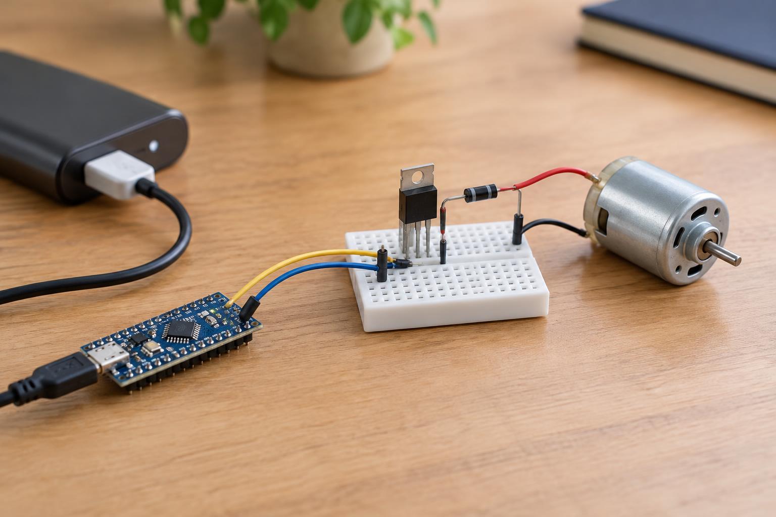
You need a 5 V brushed DC motor, a suitable 5 V supply, a PWM-capable microcontroller output, a logic-level N-channel MOSFET, a flyback diode, a gate resistor and a gate pull-down resistor. A gate resistor of roughly 100 to 330 ohms and a pull-down resistor of roughly 10 kilohms are reasonable starting points for a small circuit. Check the MOSFET’s pinout and specifications: it must switch properly at your controller’s output voltage, which might be 3.3 V rather than 5 V.
Select the supply, MOSFET, diode, wiring and any breadboard for the motor’s current, including its higher starting or stalled current—not just its normal running current. If that information is unavailable, use a known, modest motor and avoid a load that can jam it. Do not power the motor directly from a microcontroller output pin. A computer USB port or controller board’s 5 V pin may also be unsuitable for the motor’s current; use a separate, adequately rated 5 V motor supply when in doubt.
Wire the switch and protective diode
With all power disconnected, connect the motor between the supply’s positive 5 V terminal and the MOSFET’s drain. Connect the MOSFET’s source to the supply’s negative terminal. Connect the PWM output to the gate through the gate resistor, and place the pull-down resistor between gate and source. If the controller has its own supply, connect its ground to the motor supply’s negative terminal so the PWM signal has a shared reference. Do not join two positive supply outputs unless their documentation specifically allows it.
Place the flyback diode across the motor terminals. Its cathode, usually marked by a band, goes to the motor terminal connected to positive 5 V; its anode goes to the motor terminal connected to the MOSFET drain. In normal operation the diode does not conduct. When the MOSFET switches off, it provides a path for current from the motor’s inductance, helping protect the switch from a voltage spike. Reversed diode polarity can effectively short the supply when the switch turns on, so check the band before applying power.
Set up PWM and make a cautious first test
Configure the controller pin as a PWM output, start at 0% duty cycle and increase it gradually. A PWM frequency in the low kilohertz range is a practical starting point for many small motors, though audible noise, controller capabilities and MOSFET heating may influence the final choice. If the motor does not start at a low duty cycle, briefly raise the setting rather than assuming the wiring is faulty. Keep fingers, hair and loose wires away from the spinning shaft.
Before powering the circuit, inspect every connection against the MOSFET pinout and diode markings. For an initial test, leave the motor lightly loaded and run it for short periods. Disconnect power immediately if a component becomes unusually hot, wiring smells, or the motor stalls. A diode protects against switching spikes; it does not make an undersized supply, switch or wire safe.
Troubleshoot one connection at a time
If the motor never runs, disconnect power and check that the supply delivers 5 V, the controller and motor supply share ground, the MOSFET pins are correctly identified, and the PWM output is actually changing duty cycle. If the motor runs continuously, check for a drain-to-source wiring error and confirm that the gate pull-down is connected. If the controller resets when the motor starts, the supply may be sagging; a separate motor supply with shared ground may help.
If speed control is erratic, inspect loose contacts and consider whether the motor’s startup current exceeds the circuit’s ratings. Do not hold the shaft to test a stall: a stationary motor can draw substantially more current than a spinning one. Once the circuit works, secure exposed connections and keep the motor within its rated voltage and reasonable mechanical load.