What a tilt switch can tell you
A ball tilt switch is a small mechanical component that opens or closes a circuit as its orientation changes. In this project, a 3.3 V microcontroller reads the switch and changes its onboard LED to show whether the switch is closed. It is a compact way to practice digital inputs without needing a separate sensor module or display.
A tilt switch does not measure an angle. Its switching position depends on how it is mounted, and the ball can move briefly when the assembly is shaken. The result is best understood as a rough position or movement indication, not a precise level or safety-critical alarm. Choose a non-mercury, two-terminal ball tilt switch for this build; do not open the switch housing.
Gather parts and stay within the project limits
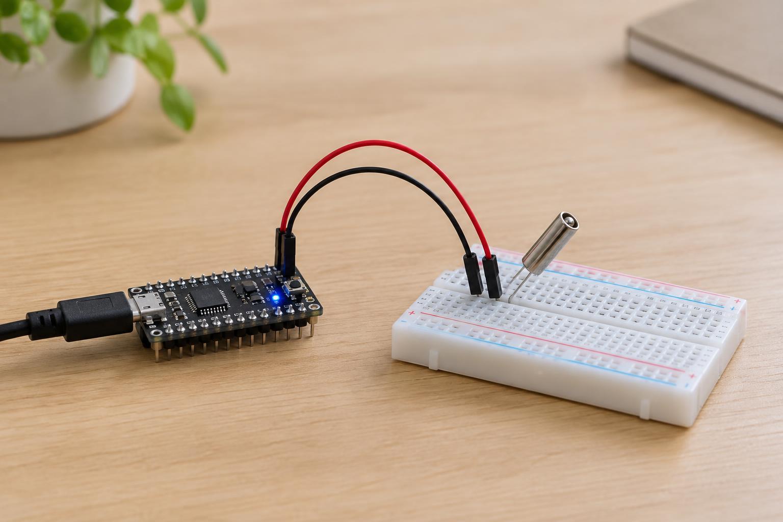
You need a 3.3 V microcontroller board with an onboard LED, a two-terminal ball tilt switch, a breadboard and jumper wires. You also need a suitable USB connection for programming and powering the board. Check the board’s pinout to identify a general-purpose input pin, a ground pin and the onboard LED designation. Board labels and LED behavior vary, so use the information for your particular board rather than assuming that every board works alike.
Keep the circuit on the board’s low-voltage side. Do not connect the switch to a household outlet, an appliance’s internal wiring or an unknown power source. Unplug the board before moving wires. A bare mechanical switch needs no separate power connection for this arrangement: it will simply connect the input pin to ground when closed. If you are reusing a switch, inspect its leads and housing first; set aside a cracked, leaking or unidentified part.
Wire the input and program the indicator
With power disconnected, place the switch on the breadboard so its two leads are not joined by the same connected row. Run one lead to a 3.3 V-compatible general-purpose input pin and the other to a ground pin. Leave the switch disconnected from the board’s 3.3 V supply pin. In the program, configure the input with the board’s internal pull-up resistor. The pull-up holds an open switch at a defined high reading; a closed switch connects the pin to ground and produces a low reading.
Configure the onboard LED as an output. In the main loop, read the switch and turn the LED on for a low reading, then off for a high reading. Some boards wire their onboard LED so a low output turns it on. If your LED behaves opposite to what you expect, check its board-specific behavior and reverse the LED output states in the program. The switch input remains active-low regardless of how the LED is wired.
Before uploading, double-check that the selected pin supports a normal digital input and that no jumper bridges the input to a supply pin. Once the program is running, slowly rotate the switch. Find an orientation that lights the LED and another that extinguishes it. Note which position corresponds to a closed switch in your particular mounting arrangement.
Make the reading steadier and diagnose surprises
Near its switching position, the ball may touch and release a contact repeatedly. An LED that flickers during movement does not necessarily mean the wiring is wrong. To make the display steadier, change the program so it accepts a new switch state only after that state has remained the same for a short interval, such as 50 milliseconds. This is called debouncing. It filters brief contact changes but also adds a small delay to the indication.
If the LED never changes, unplug the board and confirm that the switch leads occupy separate breadboard connections. Check that one lead reaches the chosen input and the other reaches ground. Then verify that the program uses that same input pin and enables its pull-up. If the input reading changes but the LED does not, check the onboard LED designation and its output polarity. Testing the input and output separately makes the fault easier to locate than rearranging wires at random.
Once it works, try mounting the switch on a small piece of card so you can repeat a tilt more consistently. Compare slow rotation with gentle shaking: the difference shows why a contact switch can indicate a general orientation without providing a reliable angle measurement. Keep the finished assembly dry, and disconnect power before storing it or changing its mounting.