Three terminals, two complementary types
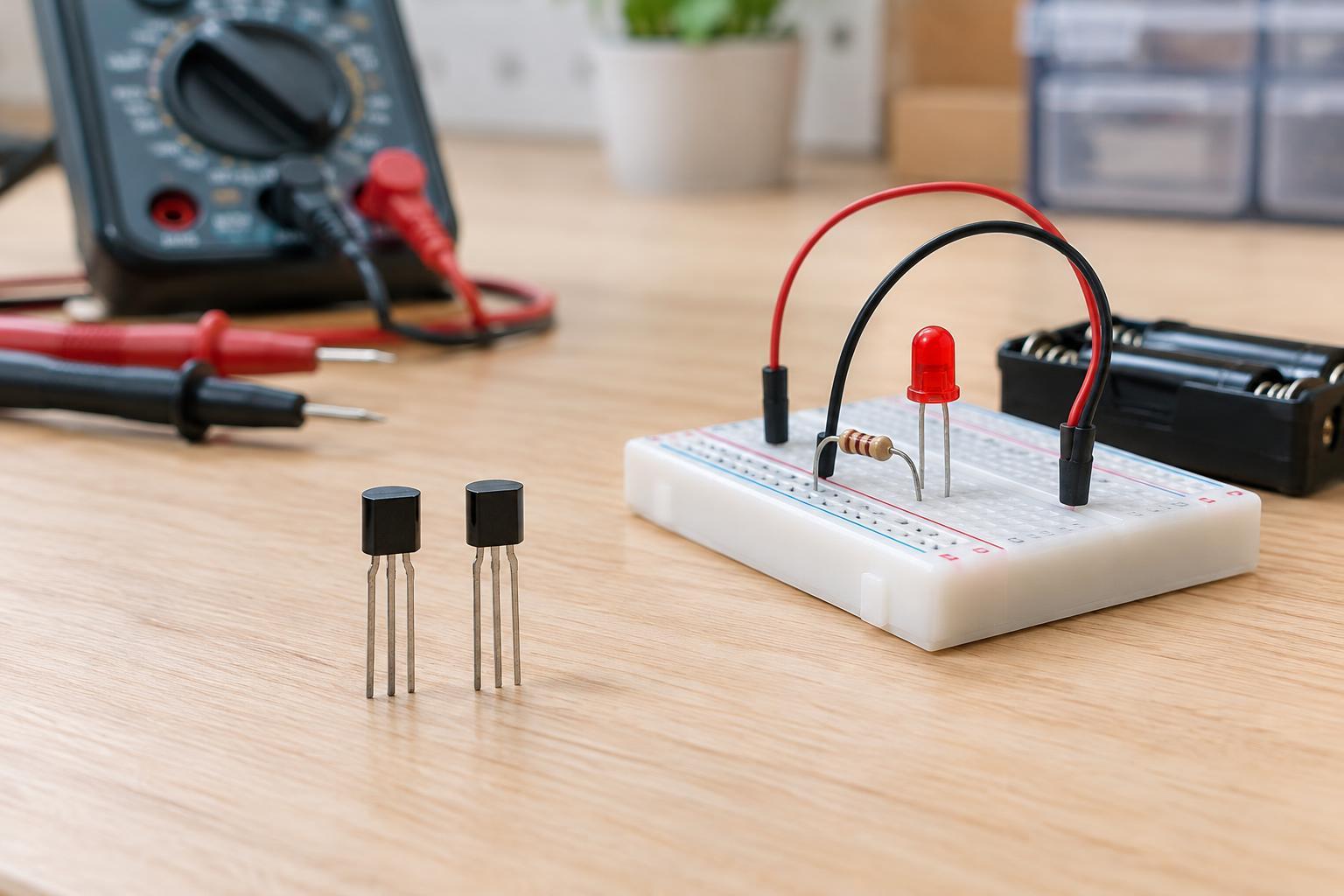
A bipolar junction transistor, or BJT, has three terminals: emitter, base, and collector. A small current through the base-emitter path helps control a larger current through the collector-emitter path. This makes a BJT useful as a switch for a small load or as part of an amplifier. The two common types, NPN and PNP, behave in complementary ways; they are not interchangeable parts.
In a typical NPN switching circuit, the emitter connects toward the negative supply and the load sits between the positive supply and the collector. Raising the base voltage above the emitter and allowing base current to flow turns the transistor on. In a typical PNP switching circuit, the emitter connects toward the positive supply and the load sits between the collector and the negative supply. Pulling the base below the emitter and allowing base current to flow turns it on. These descriptions use conventional current direction, from higher to lower electrical potential.
What base current actually does
A BJT is not a voltage-only control device. For a silicon transistor to conduct in a common switching arrangement, its base-emitter junction is forward-biased, often with a voltage difference around 0.6 to 0.7 volts. That figure is a rough guide, not a fixed turn-on threshold: it changes with current, temperature, and the particular part. The driving circuit must also provide a path for base current.
When a transistor operates in its active region, collector current is approximately base current multiplied by current gain, often labeled β or hFE. That gain varies substantially between parts and operating conditions, so it is a poor basis for assuming that a switch will always carry a particular load current. For switching, the aim is usually to provide enough base drive to bring the transistor into saturation, where increasing base current further has relatively little effect on collector current. The load and supply then largely determine that current.
A series base resistor limits current from the driving output. Without one, the base-emitter junction can draw more current than the output or transistor can safely handle. Choose the resistor using the supply and drive voltages, the expected load current, and the relevant transistor and driver ratings. Check the transistor’s power dissipation too: an undersupplied base can leave the device partly on, causing a larger voltage drop and more heating.
Choosing between NPN and PNP for a switch
An NPN transistor is often a straightforward choice for a low-side switch: the load connects to the positive rail, and the transistor completes its path to the negative rail. A logic output that can source suitable base current may drive it through a resistor, provided the output voltage, current capability, and transistor ratings fit the circuit. The controller and load supply generally need a shared reference for the base-drive voltage to be meaningful.
A PNP transistor can serve as a high-side switch, connecting a load to the positive rail. Its base must be brought close to the emitter voltage to turn it off and pulled lower to turn it on. This can complicate direct control: if the load supply voltage exceeds a controller’s output-voltage rating, connecting that output directly to the PNP base may damage the controller. An appropriate driver or a different switching arrangement may be needed. PNP does not simply mean “NPN with the wires reversed.”
A safe way to check a low-voltage example
For a beginner’s test, use only an isolated, current-limited low-voltage DC supply and a modest load such as an LED with its own series resistor. Keep this exercise away from mains wiring, unknown batteries, and high-power loads. Before connecting power, identify the transistor’s emitter, base, and collector from the specific part’s datasheet; pin order is not universal, even among parts in similar packages.
Sketch both current paths before building: the load path through collector and emitter, and the separate drive path through base and emitter. For an NPN low-side LED switch, verify that the LED resistor limits LED current and that the base has a resistor of its own. With power disconnected, check polarity and connections. Then power the circuit within its rated limits and observe whether the load responds to the base drive. If it does not, disconnect power before changing wiring.
A motor, relay, or other inductive load adds a further requirement: a correctly oriented flyback diode or other suitable suppression method to manage the voltage spike when current is switched off. Such loads are best left for a later project after their current draw, startup behavior, and protection needs are understood.
Troubleshooting without guessing
If a load stays off, check for a missing common reference, an incorrect pinout, a reversed PNP/NPN choice, or insufficient base drive. If it stays on, look for a base that is unintentionally being driven or left floating; a suitable bias resistor can establish a defined off state. If the transistor becomes warm, turn off power and check the load current, base drive, and device ratings before trying again. Thinking separately about the base-drive path and the load-current path makes most beginner BJT faults easier to locate.