What a relay does
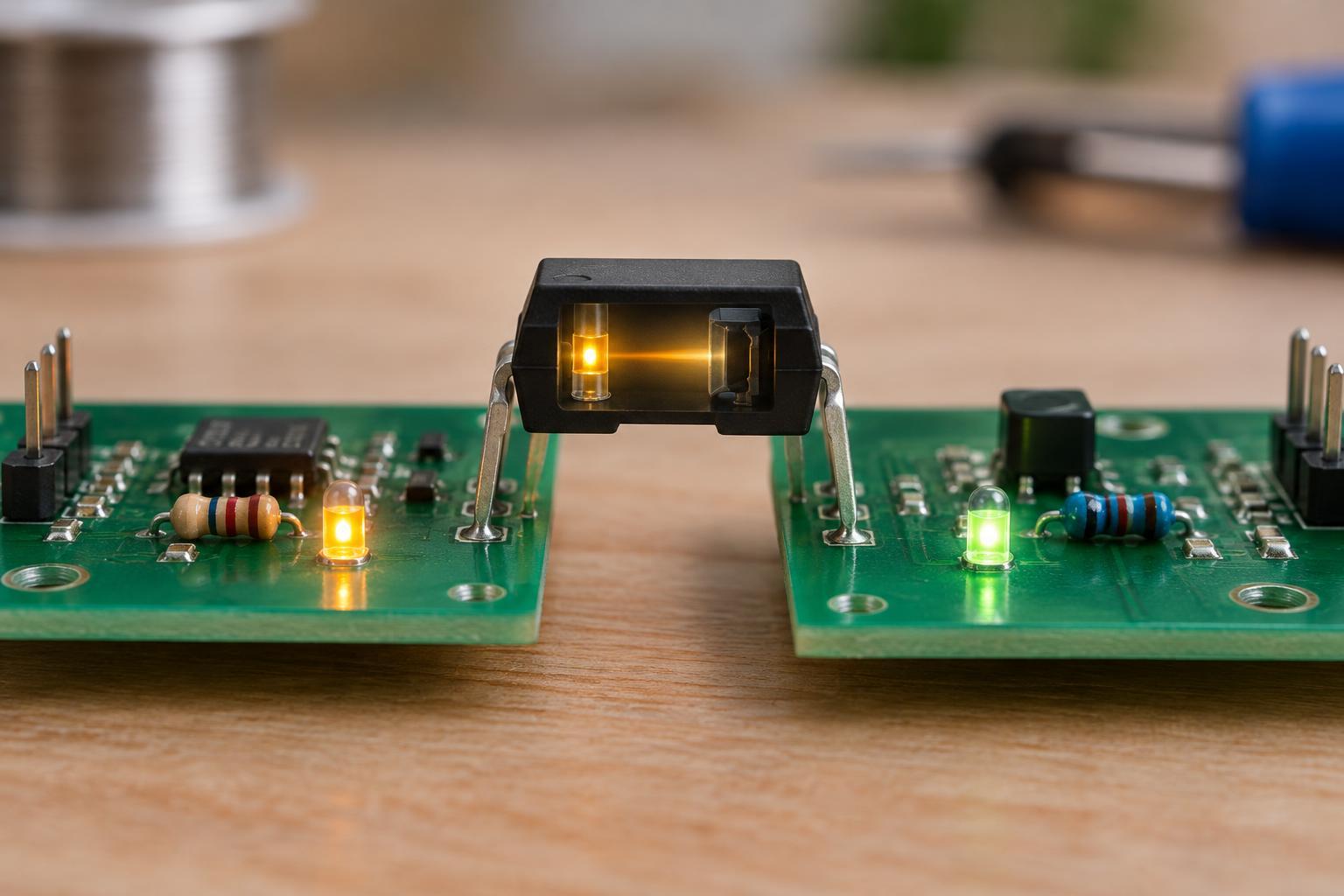
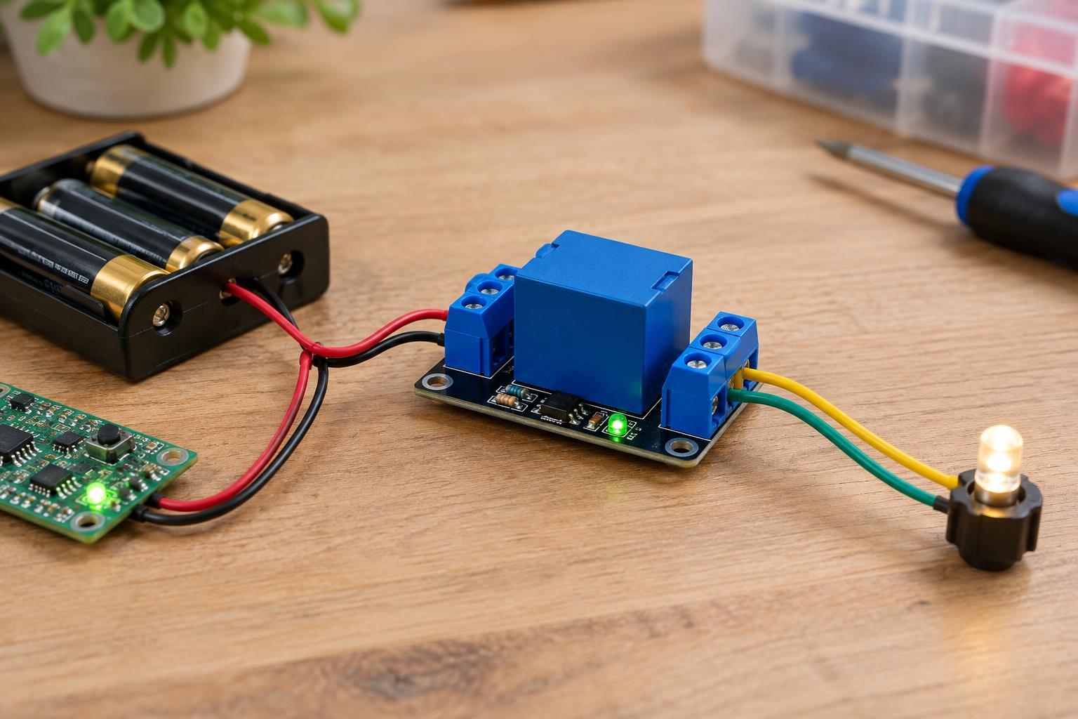
An electromechanical relay is a switch operated by an electromagnet. Applying the specified power to its coil moves a set of contacts; removing that power lets the contacts return to their resting position. This allows a control circuit to switch a separate load circuit. The two circuits are not automatically interchangeable: the coil rating describes what the control side needs, while the contact rating describes what the switching side can handle.
A basic relay may have common (COM), normally open (NO), and normally closed (NC) contact terminals. With the coil off, COM connects to NC. With the coil on, COM connects to NO. “Normally” means the unpowered state, not the state you expect the device to spend most of its time in. The contacts act as a switch; they do not supply voltage to a load on their own.
Read the coil rating first
A relay marked with a 5 V DC coil is designed to have its coil powered by a suitable 5 V DC supply. That marking does not mean its contacts can switch only 5 V, or that a 5 V microcontroller output can drive the coil directly. Check the relay’s coil current or resistance as well as its voltage: a control pin may not be able to provide the current the coil requires.
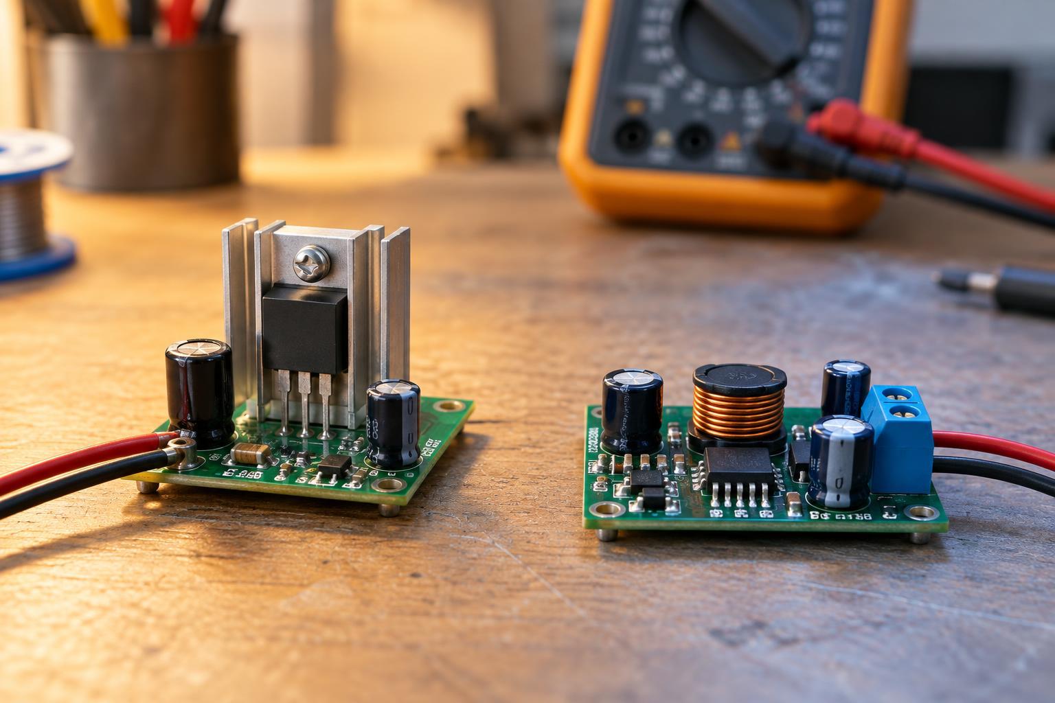
In many small projects, a transistor or suitable driver module switches the coil, using a supply that can deliver its required current. A DC coil also creates a voltage spike when switched off. A flyback diode placed across the coil in the correct orientation can protect a simple transistor driver, though it may slow the relay’s release. Some relay modules include this protection already. Check the module’s labeling or documentation before adding parts, and do not assume every module accepts the same control signal.
Coil voltage is a nominal operating rating, not a precise switching threshold. A relay may pull in at less than its rated voltage and drop out at a still lower voltage. Those thresholds vary by model and conditions. For reliable operation, use the specified supply range rather than relying on a relay that happened to click during a quick test.
Understand what contact ratings cover
Contact ratings are usually expressed as a maximum switching voltage and current, sometimes with a separate value for the type of load. Both limits matter. A contact rated for several amperes is not suitable for every circuit below that current: the voltage, whether it is AC or DC, and the load’s behavior also affect switching. Follow the rating for the particular relay and contact arrangement, rather than a number copied from a similar-looking part.
A resistive load, such as a modest low-voltage heater, is relatively straightforward to switch. A motor or solenoid can draw more current at startup and can produce a voltage spike when turned off. An LED driver or a circuit with large input capacitors may have a brief inrush current. These effects can cause contact wear or welding even when normal running current appears acceptable. DC loads can be especially difficult to interrupt because an arc does not benefit from the regular current zero-crossings of AC.
Ratings for carrying current and for repeatedly making or breaking current may differ. Mechanical contacts also wear with use, so a design that switches frequently may need a different approach, such as an appropriately chosen solid-state switch. Do not treat a printed maximum as a target operating point; allow margin for the actual load and its startup behavior.
Choose a relay for a small low-voltage project
Start with the load: note its supply voltage, normal current, likely startup current, and whether it is inductive. Then find a relay whose contacts are specified to switch that kind of load at those values. Next, choose a coil your available supply and driver can operate. Decide whether the load should be off or on when the control circuit is unpowered, and wire NO or NC accordingly. A click confirms that something moved, but it does not prove that the contacts are rated for the load.
For a learning project, keep both sides at low voltage, such as a small battery-powered control circuit switching a modest battery-powered load. Even low-voltage batteries can deliver enough current to overheat wires during a short circuit. Use wiring and connections suited to the current, add appropriate circuit protection, disconnect power before rewiring, and keep exposed conductors from touching. A relay may provide separation between circuits, but its presence alone does not make a high-voltage or mains-powered project safe.