A signal crosses, but a wire does not
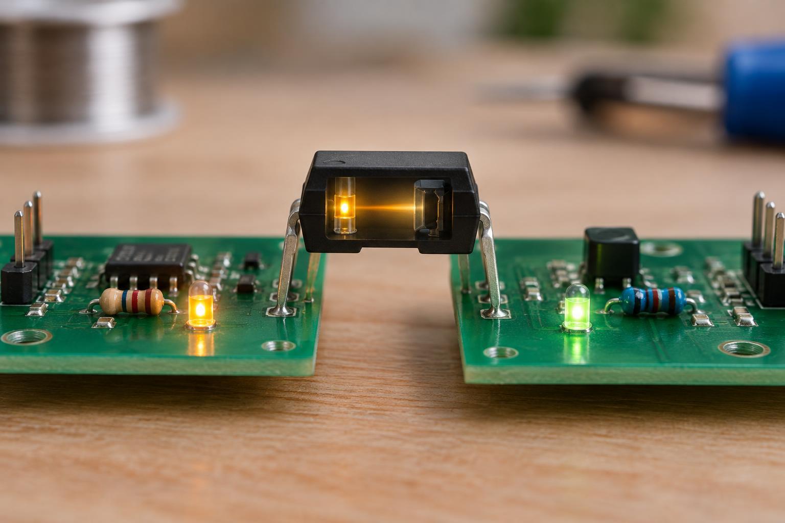
An optocoupler, also called an optoisolator, contains a light emitter and a light-sensitive device facing each other inside a package. In a common type, the emitter is an LED and the receiver is a phototransistor. Current through the LED produces light; that light makes the transistor conduct. Information can therefore pass from one side to the other without a direct conductive connection inside the device.
This separation is useful when two circuits should not share a signal-path ground. For example, a low-voltage controller might need to detect a signal from another low-voltage circuit whose ground is noisy or at a different potential. An optocoupler can reduce the need for a direct electrical connection between them. It does not create power for the receiving circuit: that side normally needs its own supply and a complete local current path.
What happens on each side
Think of the input as an ordinary LED. It has a specified polarity and needs a way to limit its current, often a series resistor in a simple low-voltage circuit. With too little current, the light may not reliably activate the output. With too much, the LED can be damaged. The required resistor depends on the input supply voltage and the device’s specified operating limits.
On the output side, a phototransistor typically acts more like a light-controlled switch than a power source. One common arrangement connects its emitter to the receiving circuit’s ground and its collector to that circuit’s supply through a pull-up resistor. When the input LED is off, the pull-up makes the collector voltage high. When the LED is on and the transistor conducts sufficiently, the collector voltage falls. In this arrangement, an active input produces a low output, so the signal is inverted.
That arrangement is only one option, not a universal pinout or wiring rule. Optocouplers come with different output devices and package connections. Check the part’s datasheet before connecting pins, and treat the input and output as distinct circuits if isolation is the goal.
Isolation has practical limits
The internal gap blocks a direct conductive path through the optocoupler, but isolation is a property of the whole design, not just the component. A wire, shared ground, conductive mounting feature or printed-circuit-board trace that bridges the two sides can defeat the intended separation. Board layout and the spacing between conductors matter, as do the operating conditions specified for the device.
An isolation-voltage figure in a datasheet should not be read as permission to connect an arbitrary hazardous voltage. Test ratings, continuous operating ratings and required spacing can describe different things. Ordinary breadboards and casual wiring are not appropriate ways to establish a safety barrier. For beginner projects, keep both sides within clearly understood, extra-low-voltage supplies; work involving mains or other hazardous energy calls for properly rated equipment and qualified design review.
Choosing a part for the signal
A key specification for a phototransistor optocoupler is current transfer ratio, or CTR. It compares output collector current with input LED current under stated test conditions. CTR is not a fixed gain you can rely on in every circuit: it varies by part, operating point and temperature, and may change with use. Design around the specified range rather than assuming the output can carry as much current as the input LED.
Speed matters too. A device suitable for slowly changing status signals may not reproduce fast pulses cleanly. Turn-on and turn-off times depend partly on the circuit around the optocoupler, including the output load resistor. Other useful datasheet checks include allowable LED current, output voltage and current limits, off-state leakage, package pinout and the specified isolation characteristics. If the task is to switch a substantial load, the optocoupler’s output may need to drive another suitable stage rather than carry the load itself.
A low-voltage way to reason through a circuit
When examining an optocoupler circuit, trace two loops separately. First, find the path that supplies and limits current through the input LED. Then find the receiving-side supply, pull-up or other load, and return path for the output device. If either loop is incomplete, the circuit cannot behave as expected. If the grounds are tied together elsewhere, the signal may still work, but the intended galvanic separation is gone.
If the output seems stuck, check the LED polarity, input current, output pinout and receiving-side pull-up before assuming the component is faulty. Also check whether the chosen part can provide enough output current for that pull-up under the specified conditions. Keeping these questions separate makes troubleshooting easier—and helps preserve the central idea of an optocoupler: light carries the signal, while each side supplies its own electrical path.